How to Read Solenoid Valve Symbols: Hydraulic and Pneumatic Valves Side by Side

Table of Content
Solenoid Valve Symbols Explained Hydraulic and Pneumatic

You open a catalog or a hydraulic circuit diagram and see a row of boxes, arrows and T-shaped marks. How do you tell where the spool sits when the solenoid is de-energized, and which ports are connected to each other?

A solenoid valve symbol uses boxes to show the spool positions, and arrows and blocking marks to show how the ports connect. Once you can read these symbols, you can tell the flow path in each valve position and the starting state when the power is off.

This article uses actual symbols from the Tai-Huei catalog to explain how to read hydraulic solenoid directional valve symbols and pneumatic solenoid valve symbols, so you can work out what a valve does straight from the drawing.

Sources: the spool function tables in the Tai-Huei G02 and G03 series catalog, and the AS/AD series pneumatic solenoid valve catalog. The spool functions described here have been confirmed by Tai-Huei engineers.


Key Points

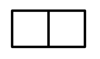
  1. Count the boxes. The number of boxes equals the number of valve positions. Each box shows how the ports connect when the spool is in that position.
  2. Check both ends. A box with a diagonal line is the solenoid operator, and a zigzag line is a spring. A valve with a solenoid at one end only is single-solenoid; a valve with solenoids at both ends is double-solenoid.
  3. On a three-position valve, read the center box first. When both solenoids are de-energized, a spring-centered spool returns to the center position. The center flow path decides whether the pump unloads and whether the cylinder can hold its position.
  4. Check the ports. Tai-Huei hydraulic solenoid directional valves have four ports: P (pressure), T (tank), and A and B (work ports).
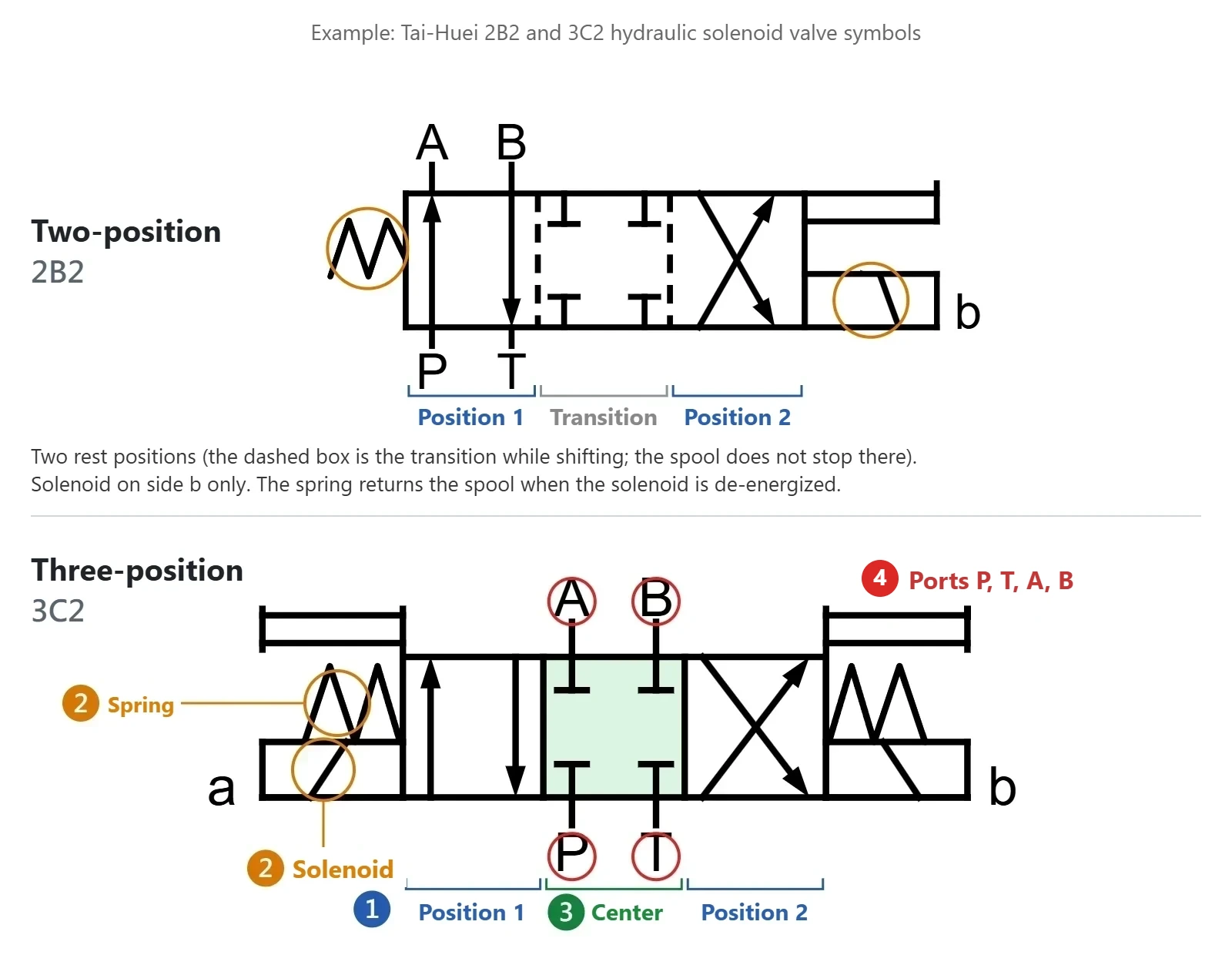
Tai-Huei 2B2 and 3C2 symbols explaining two-position and three-position solenoid valves


What Are the Parts of a Solenoid Valve Symbol?

A solenoid valve symbol is made up of boxes, arrows, blocking marks and operators. Once you know what each element means, you can read the number of positions, how the oil or air flows, and how the spool shifts and returns, straight from the catalog symbol.
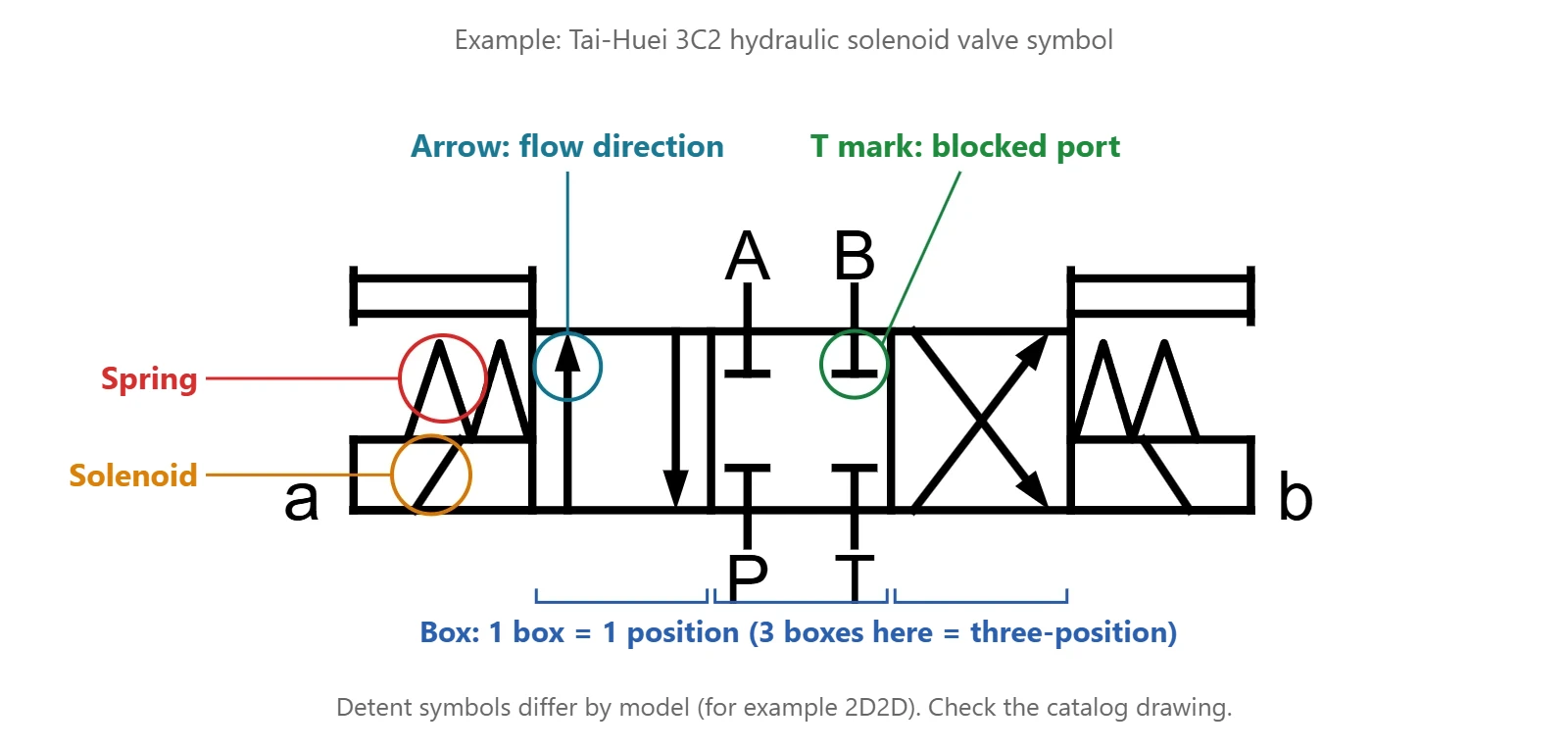
Parts of a solenoid valve symbol labeled on the Tai-Huei 3C2 spool

Symbol element

Symbol

What it means

What to watch for

Box
Box symbol: two adjacent boxes show two working positions
One working position of the spoolThe number of boxes is the number of positions: two boxes for a two-position valve, three boxes for a three-position valve.
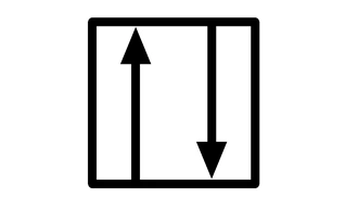
Arrow
Arrow symbol: arrows inside a box show the flow direction
Direction of oil or compressed air flowShows the flow path in that position. Read it together with the ports each arrow connects.
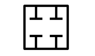
T-shaped blocking mark
T-shaped blocking mark: a T inside a box shows a blocked port
The port is blocked in that positionIf every port in the center box is drawn with a blocking mark, none of the ports connect to each other in that position.
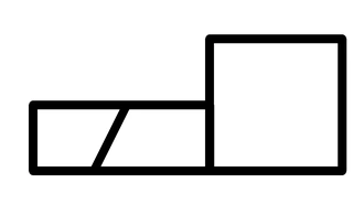
Solenoid operator
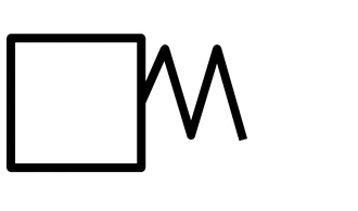
Solenoid operator symbol: a rectangle with a diagonal line
The spool is shifted by solenoid forceRead the full symbol and the catalog markings to see which side the solenoid is on. The letters a and b can also mark the operator end or the position, so do not judge the solenoid side from the letter alone.
Zigzag line
Zigzag line symbol: a spring on the side of a box
Spring returnWhen the solenoid is de-energized and no other force acts on the spool, the spring returns it to its designed position. Three-position valves usually return to center.
Detent symbol
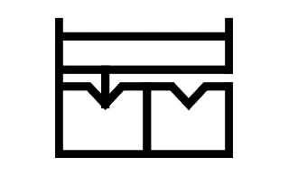
Detent symbol: frame, detent pin and V-shaped notches
Mechanical detentShows that a detent holds the spool in the selected position after it shifts, so the spool does not spring back when the solenoid is de-energized. Always check the actual symbol in the catalog.

Solenoid valve symbols are drawn to ISO 1219-1, the standard for graphical symbols of fluid power systems and components. When you read a symbol, check the full symbol, the port markings and the catalog for that model. Never judge what the valve does from a single element.


Two-Position Hydraulic Solenoid Valve Symbols: 2A2, 2B2, 2D2 and 2D2D

A two-position hydraulic solenoid directional valve has two working positions. Besides the flow paths, check where the solenoid, spring and detent are, so you know what the spool does when the solenoid is de-energized.

Spool code and description

Hydraulic symbol

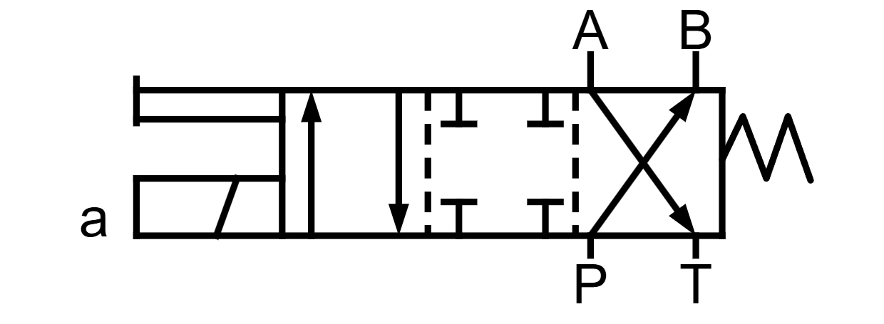
2A2: solenoid on side a, spring return

Actuation: the solenoid is on side a (the B-port side of the valve body); a spring is on the other side.

When de-energized: the spring returns the spool to its normal position.

Tai-Huei 2A2 spool symbol with a solenoid on side a and spring return

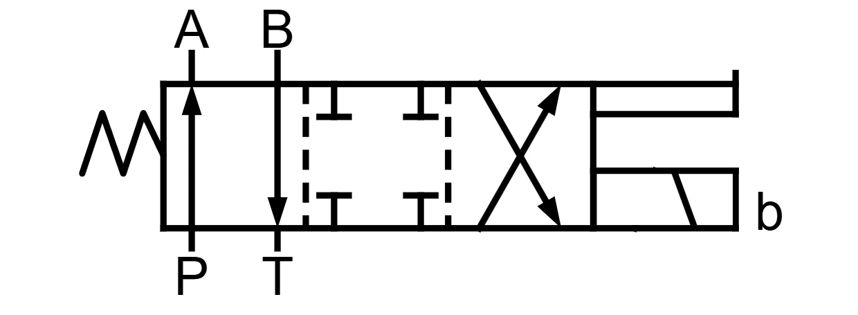
2B2: solenoid on side b, spring return

Actuation: the solenoid is on side b (the A-port side of the valve body); a spring is on the other side.

When de-energized: the spring returns the spool to its normal position.

Tai-Huei 2B2 spool symbol with a solenoid on side b and spring return

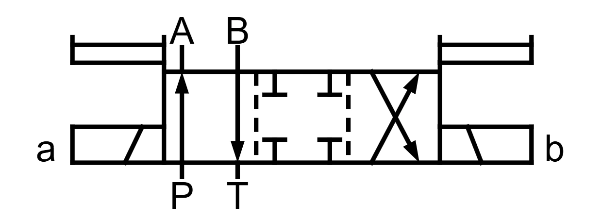
2D2: double solenoid, no detent

Actuation: solenoids on both sides, no detent and no spring return.

When de-energized: the spool stays in the last position it shifted to. It does not return on its own.

Mounting: the valve must be mounted with the spool axis horizontal.

Tai-Huei 2D2 spool symbol with double solenoids and no detent

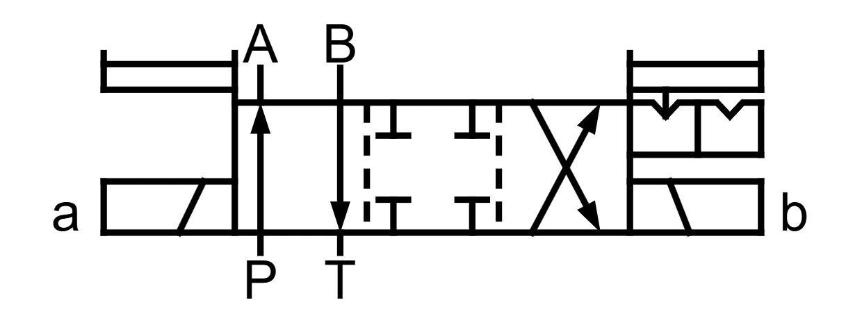
2D2D: double solenoid with detent

Actuation: solenoids on both sides with a detent and no spring return.

When de-energized: the detent holds the spool in the last position it shifted to. It does not return on its own.

Tai-Huei 2D2D spool symbol with double solenoids and a detent on side b


What Does an L at the End of the Code Mean?

Take the 2A2L and 2B2L in the Tai-Huei catalog: L stands for reverse assembly. It moves the solenoid to the other side to suit the space available on the machine.

Standard assembly

Reverse assembly (L)

2A2: solenoid on side a (B-port side of the valve body)

Tai-Huei 2A2 spool symbol with a solenoid on side a and spring return

2A2L: solenoid on side b (A-port side of the valve body)
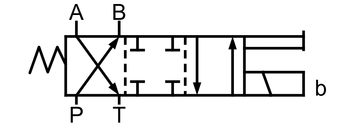
Tai-Huei 2A2L spool symbol in reverse assembly with the solenoid on side b

2B2: solenoid on side b (A-port side of the valve body)

Tai-Huei 2B2 spool symbol with a solenoid on side b and spring return

2B2L: solenoid on side a (B-port side of the valve body)
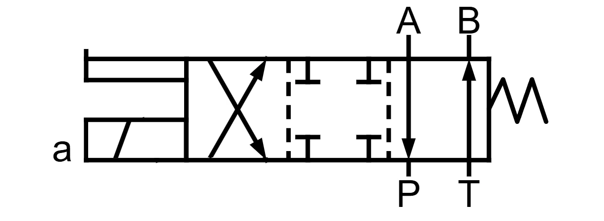
Tai-Huei 2B2L spool symbol in reverse assembly with the solenoid on side a

When selecting a valve, compare the symbol and assembly direction of that exact model to confirm the solenoid side and the spring arrangement. Do not substitute one model for another based on the code alone.


Three-Position Hydraulic Solenoid Valve Symbols: How to Read 3C Center Conditions

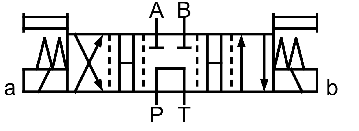
Spool codes starting with 3C indicate three-position valves with a solenoid on each side. When both solenoids are de-energized, the springs on both sides push the spool back to center. So the key to choosing a three-position valve is which ports are connected and which are blocked in the center box.

Spool code and description

Hydraulic symbol

3C2

Center: P, T, A and B all blocked (closed center).

Both cylinder ports and the pump are cut off.

Tai-Huei 3C2 spool symbol with all four ports blocked in center

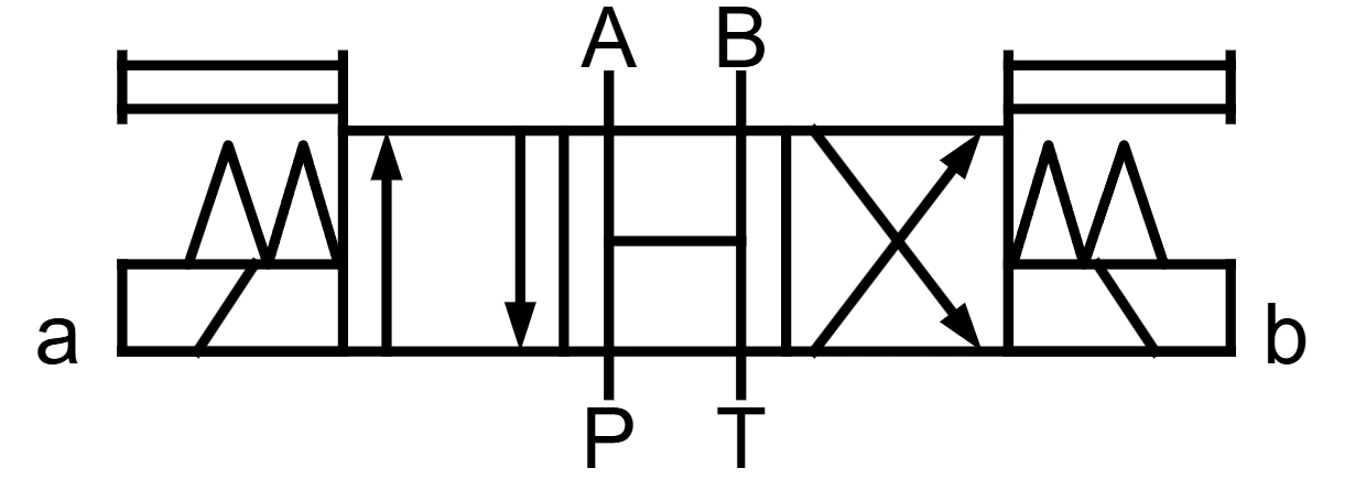
3C3

Center: P, T, A and B all connected (open center).

The pump unloads, and both cylinder ports are open to tank.

Tai-Huei 3C3 spool symbol with all four ports connected in center

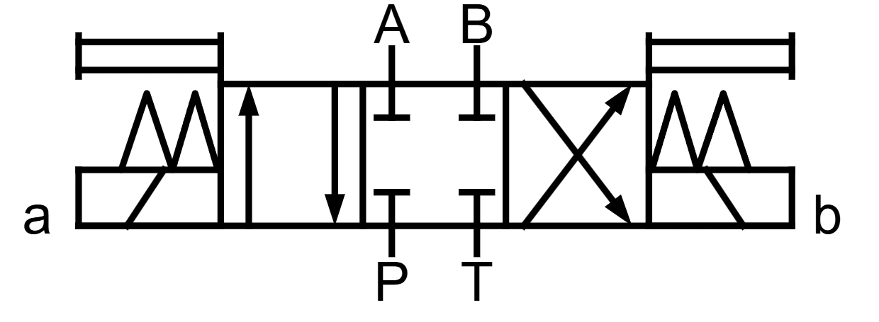
3C4

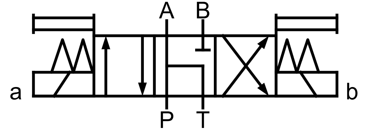
Center: P blocked; A, B and T connected (float center).

The pump does not unload. Both cylinder ports are open to tank.

Tai-Huei 3C4 spool symbol with P blocked and A B T connected in center

3C5

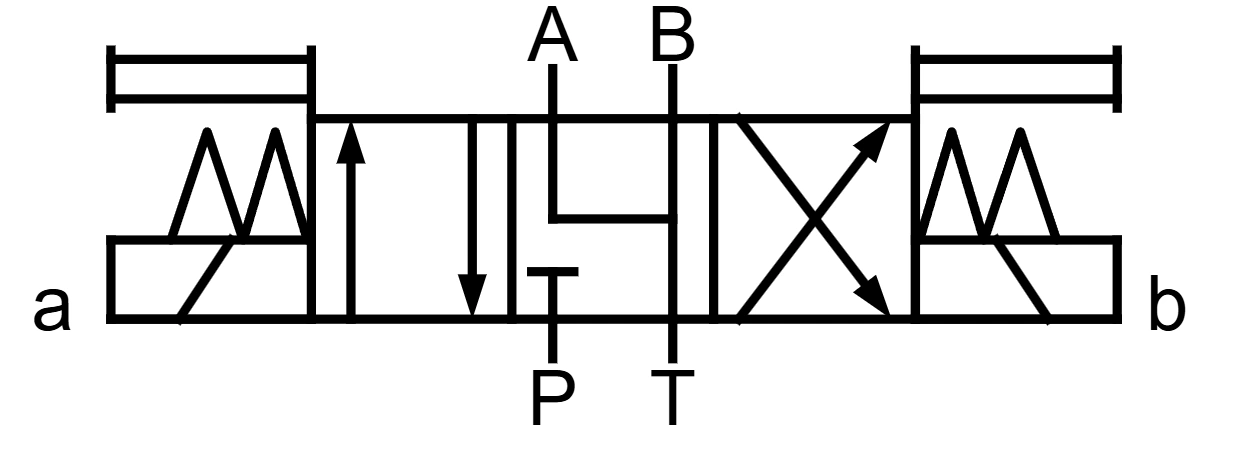
Center: P, A and T connected; B blocked.

Side A connects to the pump and tank. Side B is blocked.

Tai-Huei 3C5 spool symbol with P A T connected and B blocked in center

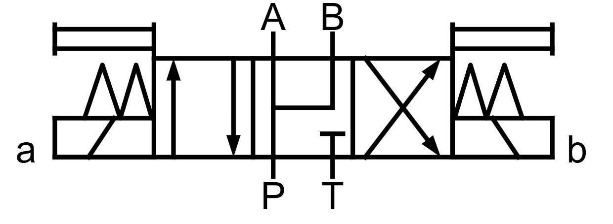
3C9

Center: P, A and B connected; T blocked (regenerative center).

Pump flow goes to both sides of the cylinder.

Tai-Huei 3C9 spool symbol with P A B connected and T blocked in center

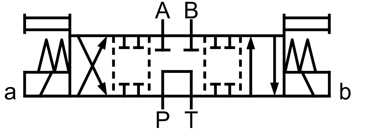
3C6

Center: P and T connected; A and B blocked (tandem center).

The pump unloads and both cylinder ports are blocked. Closed crossover: all four ports are blocked for an instant during the shift.

Tai-Huei 3C6 spool symbol with P T connected in center and a closed crossover

3C60

Center: P and T connected; A and B blocked (tandem center).

The pump unloads and both cylinder ports are blocked. Open crossover: all four ports are connected for an instant during the shift.

Tai-Huei 3C60 spool symbol with P T connected in center and an open crossover

The 3C6 and 3C60 have the same center condition. The difference is the crossover, the transition state the spool passes through while shifting: the 3C6 has a closed crossover (all ports blocked for an instant), and the 3C60 has an open crossover (all ports connected for an instant). That is why their symbols have more boxes than other three-position valves. The extra boxes show the crossover states.


Once You Can Read the Symbol, How Do You Match It to a Tai-Huei Spool Code?

Code prefix

Meaning

2ATwo-position, solenoid on side a, spring return on the other side
2BTwo-position, solenoid on side b, spring return on the other side
2DTwo-position, solenoids on both sides, no spring return (2D2 has no detent; 2D2D has a detent)
3CThree-position, solenoids on both sides, spring-centered
L at the endReverse assembly (solenoid moved to the other side)

To see the symbols for every G02 and G03 spool, open G02-G03 Spool Symbols on our Technical Support page.

The number after the prefix names the flow path. Different numbers mean different port connections, so always go by the catalog symbol. The G02 and G03 catalog lists dozens of spools, and we also design custom spools. Tell us the center condition and the de-energized state your circuit needs, and we will match them to the right spool code.
✉ Contact us

Solenoid Valve Symbol FAQ

Which center condition keeps the cylinder in place during a power failure?

Start with a center condition that blocks both A and B, such as the Tai-Huei 3C2 (all four ports blocked). The 3C6 and 3C60 also block A and B, but they connect P to T, so check whether you need the pump to unload.

Blocking A and B cuts off the return path through the directional valve on both sides of the cylinder, but it does not lock the cylinder completely. Internal clearance in a spool valve can cause leakage, and an external load can make the cylinder creep. If you need to hold position for a long time or keep a load from dropping, evaluate a pilot-operated check valve, a counterbalance valve or other load-holding measures for your system.


Where on the symbol do I look to see if the pump unloads in center?

Look at whether P and T connect in the center box. If P and T connect directly in center, pump flow can return to tank through the directional valve and the pump unloads. The actual unloading still depends on the design of the whole circuit.

Among Tai-Huei spools, the 3C3 (all ports connected), 3C6 and 3C60 all connect P and T in center, while the 3C2 and 3C4 block P in center. So do not choose on unloading alone. Also check how A and B connect and what the cylinder needs to do.


What is the difference between 2B2 and 2B2L, and which should I choose?

Both have the same spool function. The difference is which side the solenoid is mounted on: the 2B2 is the standard assembly with the solenoid on side b, and the 2B2L is the reverse assembly with the solenoid on side a.

If there is not enough room on side b of the machine but you still need the 2B2 flow path, consider the 2B2L. Before ordering, check the catalog for how the solenoid side is defined and which way the valve mounts.


Where does a 2D2 stop when the power is off?

The 2D2 is a double-solenoid design with no spring return and no detent. Once the spool shifts to a position, it stays in the last position it shifted to even after the solenoid is de-energized. It does not return to a starting position the way a spring-return spool does.

The 2D2 must be mounted with the spool axis horizontal. If you need a detent to hold the spool in position, choose the 2D2D. For both the 2D2 and the 2D2D, the state after the power is off depends on which position the spool last shifted to.


Pneumatic Solenoid Valves: How to Read 5/2 and 5/3 Symbols

Pneumatic solenoid valve symbols are read the same way as hydraulic directional valve symbols: count the boxes for the number of positions, then use the arrows and blocking marks to see how the ports connect.

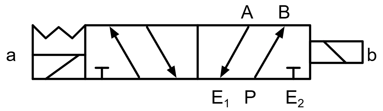
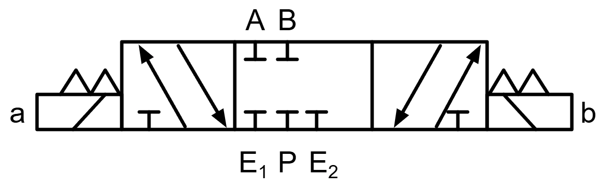
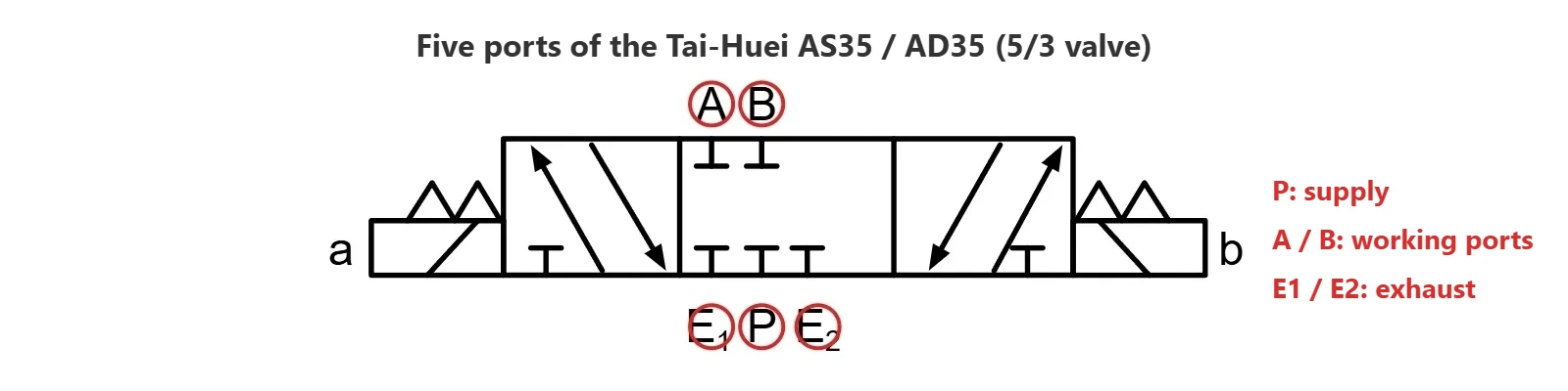
The Tai-Huei AS/AD series uses five ports: P is the supply port, A and B are the working ports, and E1 and E2 are the exhaust ports. So two boxes mean a 5/2 valve (five ports, two positions), and three boxes mean a 5/3 valve (five ports, three positions).

Five ports of the Tai-Huei AS35 and AD35 5/3 pneumatic solenoid valve

Model and description

Pneumatic symbol

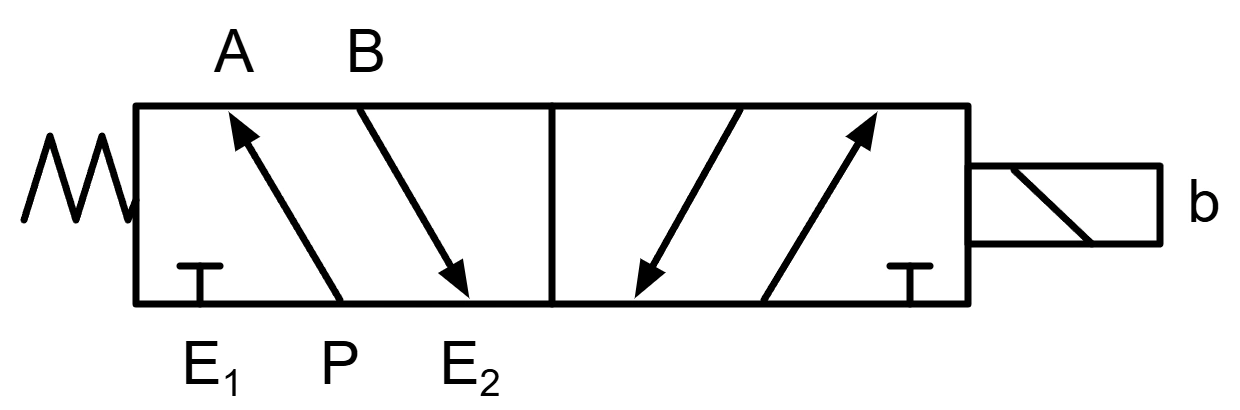
AS15/AD15: single solenoid, two-position (5/2)

Actuation: solenoid on one side, spring on the other.

When de-energized: the spring pushes the spool back to its return position, and the port connections switch with it.

Tai-Huei AS15 and AD15 single-solenoid two-position pneumatic valve symbol

AS25/AD25: double solenoid, two-position (5/2)

Actuation: solenoids on both sides, no spring return.

When de-energized: with both solenoids off, the spool stays in the last position it shifted to. It does not return on its own.

Tai-Huei AS25 and AD25 double-solenoid two-position pneumatic valve symbol

AS35/AD35: double solenoid, three-position (5/3)

Actuation: solenoids on both sides, spring-centered.

When de-energized: with both solenoids off, the spool returns to center. If all five ports in the center box are drawn with blocking marks, it is a closed-center valve with all five ports blocked.

Tai-Huei AS35 and AD35 double-solenoid three-position pneumatic valve symbol


How do I choose between a 5/2 and a 5/3 valve?

Start with whether the cylinder needs to stop mid-stroke. If it only needs to extend and retract, choose a 5/2 valve. Choose the single-solenoid AS15 or AD15 if you want a spring to return the valve to a set position when the power is off. Choose the double-solenoid AS25 or AD25 if you want two signals to control the valve separately and keep the last position when the power is off.

If the cylinder needs to stop partway, choose the 5/3 AS35 or AD35, which returns to closed center when both solenoids are de-energized.


What do 302, 303 and 304 at the end of the model number mean?

These numbers give the port size: 302 is PT 1/4 (Rc 1/4), 303 is PT 3/8 (Rc 3/8) and 304 is PT 1/2 (Rc 1/2), with effective areas of 31, 40 and 42 mm² respectively.


What are the operating pressure and temperature ranges of the AS/AD series?

According to the Tai-Huei catalog, the operating pressure is 0 to 10 kgf/cm² (approx. 0 to 0.98 MPa, 9.8 bar or 142 psi) and the operating temperature is 5 to 60°C. The response time is 30 ms or less, and the operating frequency is 360 cycles per minute.


Will the cylinder return on its own when an AS25 or AD25 loses power?

Not necessarily. In the Tai-Huei AS/AD lineup, the AS25 and AD25 are double-solenoid two-position valves. When both solenoids are de-energized, the spool stays in the last position it shifted to and does not return on its own.

If you want a spring to push the valve back to a set position when the power is off, consider the single-solenoid, spring-return AS15 or AD15. Keep in mind that a returned spool does not guarantee the cylinder returns. What the cylinder actually does still depends on the valve port connections, the air supply and the load.


What state are the five ports in when both AS35 or AD35 solenoids are de-energized?

The AS35 and AD35 are double-solenoid, three-position (5/3) valves. When both solenoids are de-energized, the springs push the spool back to center, where all five ports are blocked. This is called a closed center.

A closed center can stop the cylinder mid-stroke, but it is not a mechanical lock. If the machine has a vertical load, a risk of a falling load or a personnel safety concern, add a mechanical lock or other safety measures.

For the difference between direct-acting and pilot-operated pneumatic valves, plus port size and flow selection and how to troubleshoot a sticking valve, see Comprehensive Selection Guide for Pneumatic Solenoid Valves: Principles, Specifications & Troubleshooting.


Further Reading

References

ISO 1219-1:2012 Fluid power systems and components — Graphical symbols and circuit diagrams — Part 1

ISO 4401:2005 Hydraulic fluid power — Four-port directional control valves — Mounting surfaces