
G02, G03, G04 and G06 are the common frame sizes for hydraulic solenoid-operated directional control valves. Each corresponds to a different ISO 4401 mounting interface and a different flow range. Beyond the interface itself, the sizes differ in the flow they can handle and the systems they suit. This guide explains the characteristics and selection rules for each size, so you can match a valve to your actual peak flow and your existing ISO 4401 subplate pattern.
Valve designations: Japanese (G) vs. American (D)
Before reviewing individual sizes, it is important to understand the difference between the G and D prefixes, as this makes it easier to interpret catalogs and machine drawings from different manufacturers.
Take G02 and D03. Customers often ask: which one do I actually need — G02 or D03? Some drawings specify G02, some catalogs list D03, and it is easy to assume these are two different products.
G prefix — the Japanese convention, used by manufacturers such as Yuken and Daikin. G stands for gasket mounting. The valve is installed on a subplate or manifold and sealed with an O-ring. 02 denotes the 1/4" size class.
D prefix — the American convention, used by manufacturers such as Vickers and Parker. D stands for Directional Control Valve. 03 is the NFPA size code.
G02 and D03 therefore differ only in naming convention. Both correspond to the same ISO 4401 mounting interface, with identical bolt patterns, port arrangements and subplate dimensions, and are directly interchangeable.
(Note: Tai-Huei model numbers use the Japanese G prefix throughout.)
G02 to G06: complete size and flow reference
Once the mounting interface is confirmed, flow rate becomes the critical sizing factor. Undersizing the valve produces a large pressure drop across the ports, wasting energy and raising oil temperature, which in turn affects system efficiency and stability. Oversizing adds cost, takes up space and consumes energy unnecessarily. Size the valve to the system’s actual peak flow requirement — neither short of it nor far beyond it.
Valve Size Code | US Standard (NFPA) / European Standard (CETOP) | ISO 4401 Mounting Surface | Typical Port Size (Reference) | Maximum Flow Rate | Maximum Working Pressure (bar) | Maximum Allowable Back Pressure (kgf/cm²) | |
|---|---|---|---|---|---|---|---|
G02 | D03 / CETOP 3 | ISO 4401-03 | 1/4" | 60 L/min | 315 | 70–160 | |
G03 | D05 / CETOP 5 | ISO 4401-05 | 3/8" | 100 L/min | 315 | 70–160 | |
G04 | D07 / CETOP 7 | ISO 4401-07 | 1/2" | 300 L/min | 315 | External Drain: 210 | Internal Drain: 140 |
G06 | D08 / CETOP 8 | ISO 4401-08 | 3/4" | 500 L/min | 315 | External Drain: 210 | Internal Drain: 140 |
(Note: the figures above are reference values for standard Tai-Huei valves. For actual flow capability, refer to the ΔP–Q curve for the specific spool.)
G02 (D03) — the standard choice for low-flow systems (direct-acting)
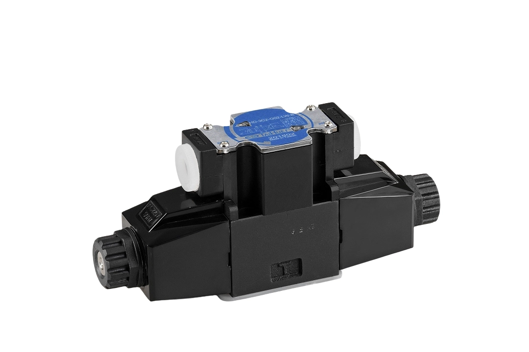
G02 (D03) is the most widely used frame size in low-flow hydraulic systems. The mounting interface conforms to ISO 4401-03 (CETOP 3 / NFPA D03), port size is 1/4", maximum flow is 60 L/min and maximum working pressure is 315 bar.Its compact body and moderate flow capacity make it suitable for small hydraulic equipment and auxiliary control circuits.
G02 uses a direct-acting solenoid design, in which the solenoid drives the spool directly. The small body and fast response suit low- to medium-flow control, and the size is widely used in compact hydraulic equipment, auxiliary circuits, and as the pilot valve for larger pilot-operated directional valves.
View Complete Specifications of the G02/D03 Series
G03 (D05) — the standard choice for medium-flow systems (direct-acting)
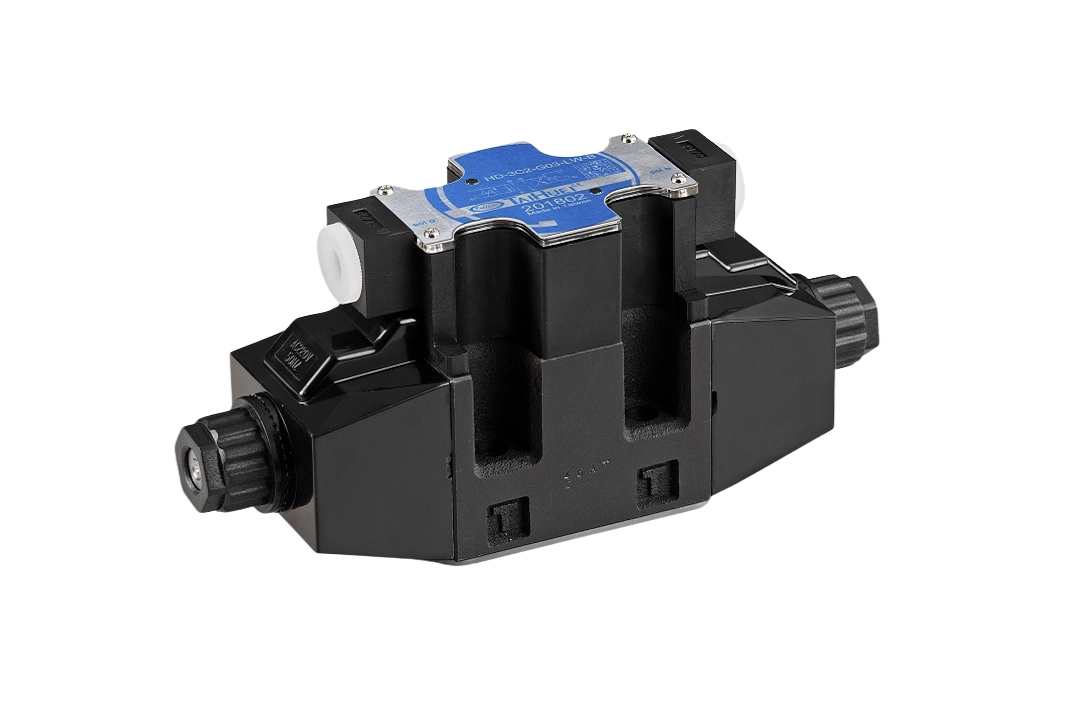
G03 (D05) is the most widely used frame size in medium-flow systems. The mounting interface conforms to ISO 4401-05 (CETOP 5 / NFPA D05), port size is 3/8", maximum flow is 100 L/min and maximum working pressure is 315 bar.
G03 is also direct-acting, but offers greater flow capacity than G02, making it suitable for systems requiring higher flow capacity.Applications include machine tools, plastics machinery, general industrial machinery and the main control circuits of medium-sized hydraulic equipment.
View Complete Specifications of the G03/D05 Series
G04 (D07) — high-flow systems (pilot-operated)
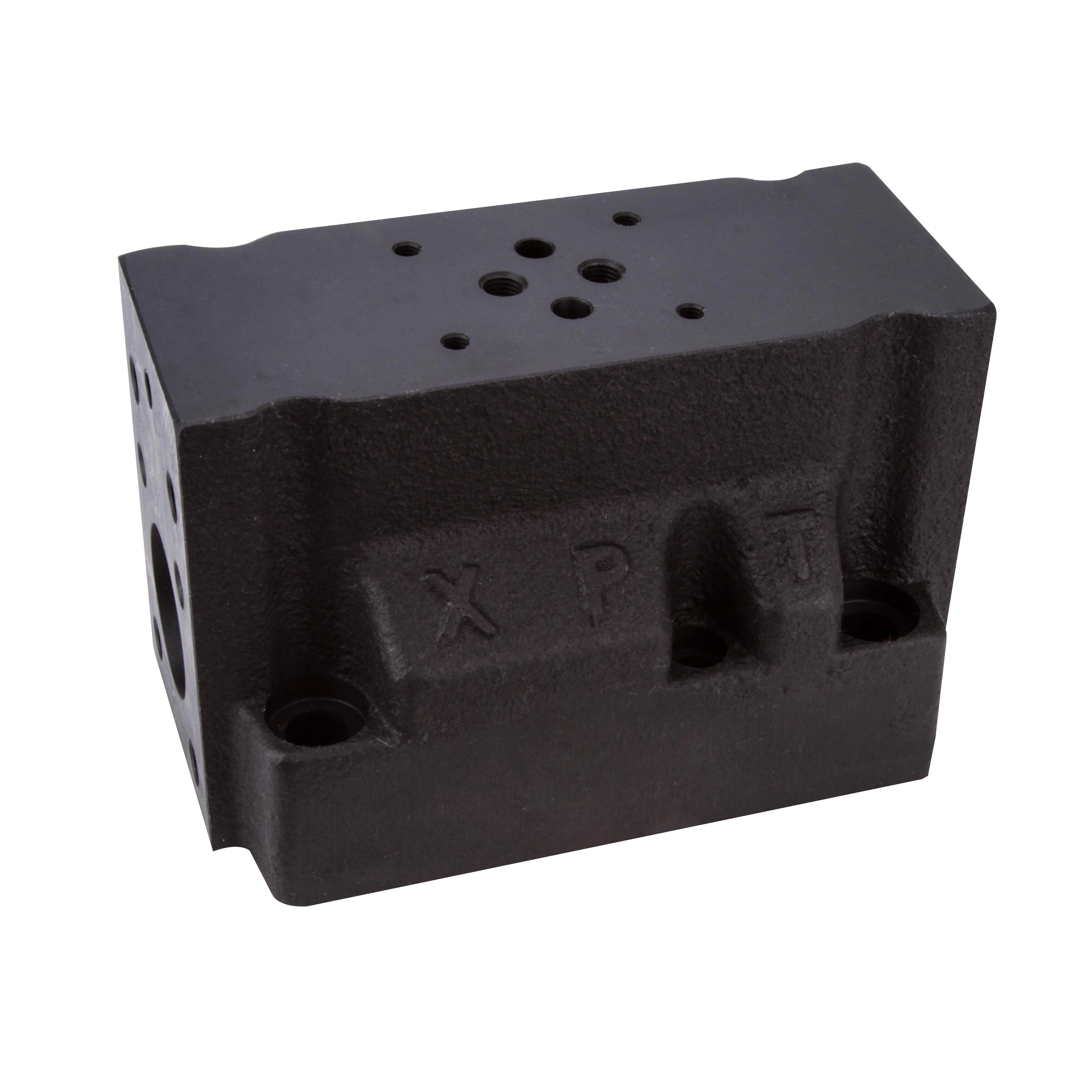
G04 (D07) suits high-flow hydraulic systems. The mounting interface conforms to ISO 4401-07 (CETOP 7 / NFPA D07), port size is 1/2", maximum flow is 300 L/min and maximum working pressure is approximately 315 bar.
This size is widely specified for hydraulic presses, hydraulic power units, steel plant equipment and other high-flow main control circuits, where it balances flow capacity with spool shifting stability — which is why it is widely used on larger machinery.
Construction and spool configuration.
G04 (D07) uses a pilot-operated design: a G02 (D03) solenoid valve mounts on top of the main body and acts as the pilot valve. The G02 controls the pilot circuit, and pilot pressure shifts the main spool. This reduces hydraulic shock during high-flow switching and improves both shifting stability and service life. Single-solenoid configuration uses main spool 2B2; double-solenoid configuration uses main spool 3C4.
View Complete Specifications of the G04/D07 Series
G06 (D08) — very high flow systems (pilot-operated)
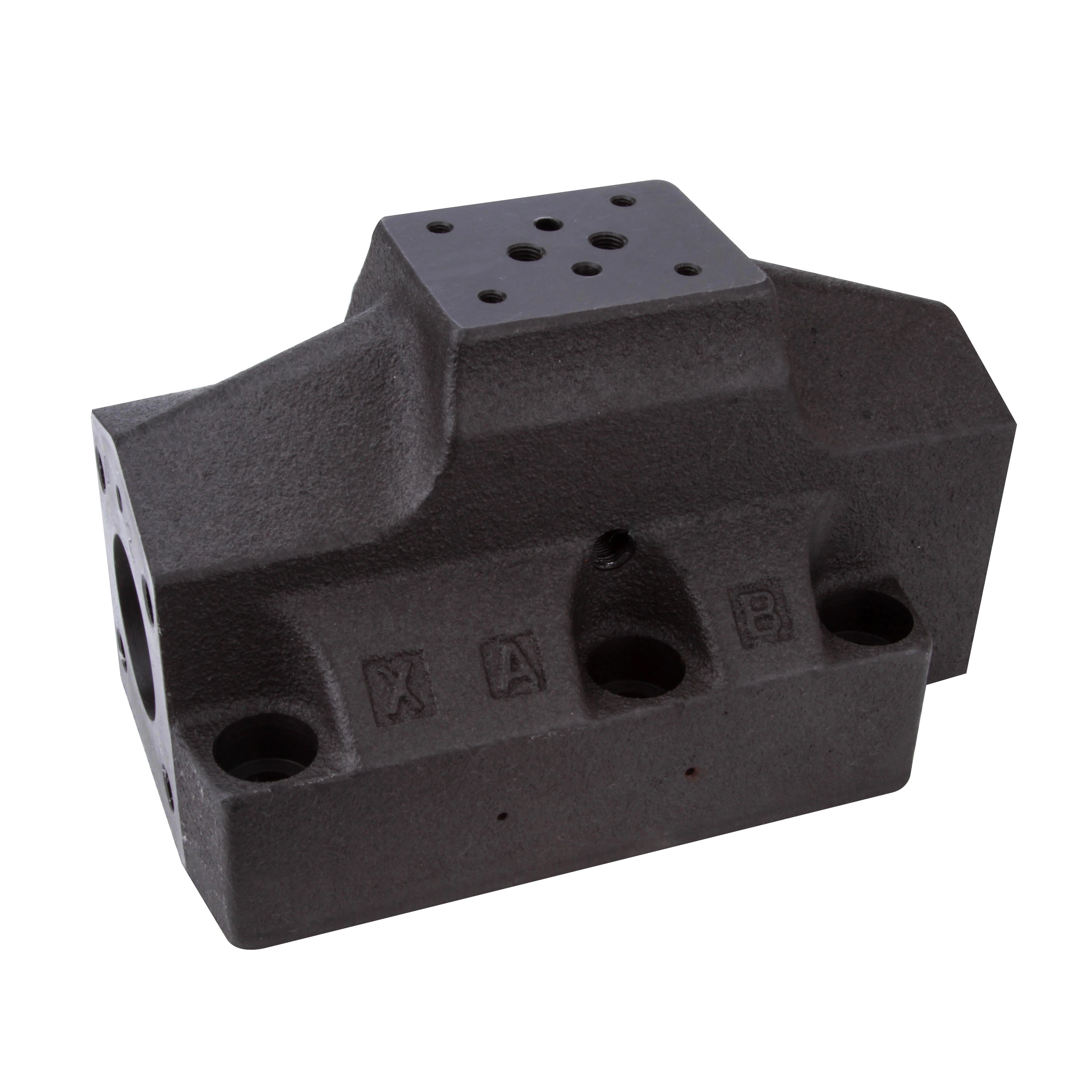
G06 (D08) has the highest flow capacity among the four standard sizes. The mounting interface conforms to ISO 4401-08 (CETOP 8 / NFPA D08), port size is 3/4", maximum flow is 500 L/min and maximum working pressure is approximately 315 bar.
G06 is used mainly in heavy hydraulic equipment, marine machinery, steel plant equipment and large hydraulic power units — applications requiring high flow, high load capacity and continuous operation.
Construction and spool configuration.
G06 (D08) is pilot-operated, with a G02 (D03) solenoid valve mounted on top as the pilot valve. The G02 controls the pilot circuit so that the main spool shifts smoothly under high flow, reducing shock and improving system reliability. Single-solenoid configuration uses main spool 2A2; double-solenoid configuration uses main spool 3C4.
View Complete Specifications of the G06/D08 Series
Direct-acting vs. pilot-operated: what actually differs
The choice of construction is driven by system flow and valve size. At low flow, a direct-acting solenoid can shift the spool using magnetic force alone — a simple design with fast response. As frame size and flow increase, however, the hydraulic forces acting on the spool also increase, and relying solely on solenoid force to shift the spool results in higher shifting resistance and greater hydraulic shock.
A pilot-operated valve instead uses a pilot circuit to move the main spool, using a small control force to command a much larger flow path. The design is more complex, but under high flow it delivers noticeably smoother shifting, lower pressure shock and better operating stability.
In the Tai-Huei range:
G02 (D03) and G03 (D05) are direct-acting, suited to low- and medium-flow control, with fast response and straightforward maintenance.
G04 (D07) and G06 (D08) are pilot-operated, suited to high-flow systems, reducing shifting shock and improving stability on larger machinery.
The following comparison highlights the key differences between direct-acting and pilot-operated solenoid valves, including flow capacity, response time, and suitable applications.
| Comparison Item | Direct-Acting Solenoid Valve | Pilot-Operated Solenoid Valve |
|---|---|---|
| Applicable Flow Range | G02 (D03), G03 (D05) | G04 (D07), G06 (D08) |
| Switching Shock | The spool is directly affected by hydraulic flow forces, resulting in more noticeable spool shifting shock at high flow rates. | The main spool is controlled through pilot pressure, reducing spool shifting shock and providing smoother operation. |
| Response Speed | Faster switching response due to direct solenoid actuation. | Slightly slower than direct-acting valves due to the time required to establish pilot pressure. |
| Typical Applications | Small hydraulic equipment, auxiliary functions of machine tools, small presses, and other low-to-medium flow control circuits. | Large stamping equipment, hydraulic power units, heavy machinery, and other high-flow main control circuits. |
| Minimum Required Pilot Pressure | Not required. The spool can be directly shifted by electromagnetic force. | Requires minimum pilot pressure (typically approximately 4–5 kgf/cm²). |
Note:
Direct-acting valves are preferred when fast response and reliable operation at low flow rates are required, while pilot-operated valves are more suitable for high-flow hydraulic systems where smooth operation and reduced switching shock are critical.
Further reading: Why Hydraulic Solenoid Valve Coils Overheat and Burn Out: Causes, Prevention and Selection Guide
Points to watch when sizing a valve
In maintenance and system design alike, it is common to select a replacement valve based on line size alone, or on what the existing valve looks like. In reality, sizing requires more than matching the mounting interface — actual flow demand, operating conditions and system behavior all matter.
Size to peak instantaneous flow, not pump displacement
The actual flow passing through the valve can exceed pump flow, depending on circuit design. In regenerative circuits, or with large-bore cylinders, the return flow during retraction can be considerably higher. Sizing from pump displacement alone risks excessive pressure drop and flow velocity, producing noise, vibration and reduced system efficiency. Size to the maximum instantaneous flow in the circuit.
An undersized valve raises pressure drop and flow forces
When the valve bore is too small, oil passing through the ports at high velocity creates a large pressure drop and increases the flow forces acting on the spool. Under high pressure and high cycling rates, excessive flow force can make shifting sluggish, increase the load on the solenoid, and indirectly raise solenoid coil temperature — shortening valve life. Choosing the right size reduces pressure loss and improves stability at the same time.
High-flow systems need shock to be assessed
In G04 and G06 applications, controlling high flow with a direct-acting valve can generate significant hydraulic shock at the moment of shifting, shortening the life of both piping and equipment. For high-flow systems, a pilot-operated directional valve is normally evaluated, using the pilot circuit to move the main spool for smoother shifting and lower pressure shock.
Worked example: return flow amplification from cylinder area ratio
Consider a system with a 45 L/min pump.
Extension stroke.
Oil flows through the valve into the cap end, so the flow through the valve equals pump flow: Q = 45 L/min. Since G02 is rated at 60 L/min, G02 is adequate for the extension stroke.
Retraction stroke.
If the ratio of full piston area to effective rod-side area is 2:1, then at the same piston velocity the cap end discharges twice the volume the rod end receives.
So while the pump still delivers 45 L/min to the rod end, the return flow leaving the cap end through the valve is 45 × 2 = 90 L/min.
Return flow through the valve has now reached 90 L/min — well beyond the 60 L/min rating of G02.
Keeping a G02 here would produce a large pressure drop on the return side, slowing retraction, increasing energy loss, raising oil temperature and, in severe cases, affecting system stability.
This application requires a G03 (D05), rated at 100 L/min, to keep return flow moving freely. Many machines are designed with the directional valve sized from pump flow alone, overlooking the return-flow amplification caused by the cylinder area ratio. This is an inherent geometric property of the retraction stroke — not a regenerative-circuit effect — and it is one of the most common sizing errors seen in the field.
Further reading: Hydraulic Solenoid Valve Connectors: Comparing 5 Wiring Types, IP Ratings and Selection Criteria
Valve sizing in four steps
1.Establish the peak instantaneous flow.
Do not size from pump displacement. Determine the maximum instantaneous flow actually passing through the valve. In regenerative circuits, during retraction of large-bore cylinders, or when several actuators move simultaneously, instantaneous flow can exceed rated pump flow.
2.Find the matching size code.
Compare your calculated peak flow against the rated flow column and choose the smallest size that meets it. This avoids the pressure drop and heat of an undersized valve, and the added cost and slower response of an oversized one.
3.Confirm the mounting interface against your existing subplate.
Check that the ISO 4401 code matches. G-series and D-series designations usually indicate the same interface, but confirm the ISO size to be certain the replacement will fit.
4.Assess whether a pilot-operated valve is required.
When specifying G04 or G06, evaluate direct-acting versus pilot-operated construction. High-flow systems generally call for a pilot-operated design to reduce shifting shock and improve stability.
Technical support and sizing enquiries
Unsure how to calculate the instantaneous flow in your system, or need a special spool or pressure configuration? Tai-Huei has over 50 years of experience in hydraulic valve manufacturing and system integration, and offers a full range of ISO 4401 solenoid directional valves. Send us your hydraulic schematic or operating requirements and our engineering team will provide a sizing assessment and technical support.