
In the field of industrial automation, a Pneumatic Solenoid Valve is an important component used to control the direction of pneumatic systems and the flow of compressed air. Improper valve selection may result in excessive pressure drop, delayed cylinder movement, solenoid valve sticking, and even affect the overall operational stability of the equipment.
Are you experiencing unstable pneumatic system operation, insufficient response speed, or difficulty selecting the right specifications for the AS and AD Series pneumatic solenoid valves? Based on years of experience in pneumatic and hydraulic systems, the Tai-Huei team has compiled practical selection guidelines covering operating principles, port sizes, positions, voltage, and operating conditions, while also sharing common faults and maintenance considerations.
In just a few minutes, you can understand the correct selection methods, reduce equipment problems caused by incorrect specifications, and improve the stability and operating efficiency of your pneumatic system.
What Is a Pneumatic Solenoid Valve? Understanding Its Operating Principles and Core Functions
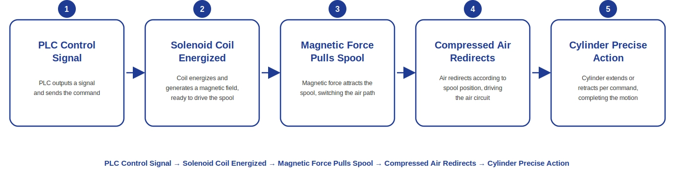
A Pneumatic Solenoid Valve is an automated pneumatic control component that uses electromagnetic force generated by a solenoid to drive the spool, thereby controlling the direction, opening, or closing of compressed air flow. Its core function is to precisely control the direction and operating frequency of actuators such as pneumatic cylinders and pneumatic valves.
In modern industrial automation equipment, compressed air is widely used as a clean and efficient power source for clamping, pushing, lifting, and other operations. However, compressed air cannot determine its direction automatically. It must rely on a solenoid coil to receive an electrical signal from a PLC or controller. When the coil is energized, the magnetic force generated moves the spool, changes the internal flow passages, and enables automatic switching within the pneumatic circuit.
What Is the Difference Between Direct-Acting and Pilot-Operated Pneumatic Solenoid Valves?
Depending on the internal actuation method of the valve, pneumatic solenoid valves can generally be divided into two main types: Direct-Acting and Pilot-Operated. The main difference between them is whether the electromagnetic force directly actuates the spool or whether compressed-air pressure is used to actuate the main spool.
Direct-Acting Solenoid Valves
A direct-acting solenoid valve uses magnetic force generated directly by the solenoid coil to move the spool or sealing element and switch the pneumatic circuit. It does not require system pressure to operate.
Therefore, it can operate normally even under zero differential pressure or low-pressure conditions. Certain products designed for vacuum applications can also be used in vacuum systems. Because there is no need to establish a pressure differential through a pilot air circuit, direct-acting solenoid valves generally provide faster response characteristics.
However, because the main spool is driven directly by electromagnetic force, the required electromagnetic force increases as the valve orifice size and flow requirements increase. This places greater demands on coil size, power consumption, and heat dissipation.
Therefore, direct-acting solenoid valves are generally more suitable for small-port and low-to-medium-flow applications.
(Using Tai-Huei’s AD/AS Series as an example, specifications such as 302 (PT 1/4"), 303 (PT 3/8"), and 304 (PT 1/2") all adopt a direct-acting design.)
Pilot-Operated Solenoid Valves
A pilot-operated solenoid valve does not use the solenoid coil to directly actuate a large main spool. Instead, electromagnetic force is first used to control a smaller pilot orifice, and the pressure differential generated by compressed air is then used to drive the main spool and complete directional switching.
Through this method, a relatively small electromagnetic control force can be used to actuate a larger main spool. This makes it possible to provide greater flow capacity while maintaining a reasonable coil size, making pilot-operated valves suitable for high-flow applications such as medium-to-large pneumatic equipment and automated production lines.
Because pilot-operated solenoid valves rely on compressed air to establish sufficient pressure differential, they generally have a minimum operating pressure requirement. The actual value varies depending on the valve structure and product specifications.
When the supply pressure is insufficient, the main spool may fail to shift properly or may operate unreliably. In addition, pilot-operated solenoid valves typically contain structures such as pilot orifices, pistons, or diaphragms, making their construction relatively more complex. Their actual size also varies depending on product design and flow specifications.
How Should You Choose Between Direct-Acting and Pilot-Operated Valves?
When selecting a pneumatic solenoid valve, the choice can be determined based on the equipment’s operating pressure, flow requirements, and response speed:
- Operation is required under low pressure or zero differential pressure → Direct-Acting
- Higher flow capacity is required → Pilot-Operated
- Fast response is required → Direct-Acting generally offers an advantage
- Medium-to-large pneumatic equipment → Pilot-Operated is generally more suitable
- System pressure is unstable or may occasionally be unavailable → First confirm whether the minimum operating pressure requirements of a pilot-operated valve can be met
Therefore, when selecting a pneumatic solenoid valve, it is not sufficient to consider only the connection size or valve port size. Operating pressure, flow rate, response speed, and control method must also be confirmed in order to select a valve suitable for the equipment.
Direct-Acting Solenoid Valve | Pilot-Operated Solenoid Valve | |
|---|---|---|
Spool actuation method | The magnetic force generated by the solenoid coil directly actuates the spool. | The solenoid coil controls the pilot orifice, while the pressure differential generated by compressed air actuates the main spool. |
Operating pressure requirements | Can operate at 0 bar or zero differential pressure, depending on the actual product specifications. | Must meet the minimum operating pressure specified for the product. The actual value depends on the valve type. |
Flow capacity and port size | Generally smaller and suitable for small-port, low-flow circuits. | Generally capable of providing greater flow capacity and suitable for medium-to-large pneumatic equipment. |
Coil power consumption and heat generation | Because the spool is directly actuated, larger valves generally require greater electromagnetic force. | The main spool is actuated by pneumatic pressure differential, while the solenoid coil primarily controls the pilot air circuit, making this design generally more suitable for high-flow applications. |
Response speed | Generally faster. Actual response time depends on the product structure. | Response speed is affected by operating pressure, valve structure, and pneumatic circuit conditions. |
Typical applications | Small pneumatic cylinders, low-pressure equipment, vacuum systems, analytical instruments, and similar applications. | Automated production lines, packaging machinery, medium-to-large pneumatic cylinders, and pneumatic equipment requiring higher flow capacity. |
Pilot-operated pneumatic solenoid valves are widely used in medium-to-large automated equipment and pneumatic systems requiring higher flow capacity. They use the pressure differential generated by compressed air to actuate the main spool, while the solenoid coil is responsible only for controlling the pilot air circuit. This allows greater flow output to be achieved with relatively small electromagnetic control force.
In comparison, direct-acting solenoid valves do not rely on system pressure for operation and are more suitable for low-pressure applications, zero-differential-pressure conditions, or applications requiring fast response.
When selecting a pilot-operated solenoid valve, it is necessary to confirm whether the system supply pressure meets the minimum operating pressure specified for the product. For vacuum applications, low-pressure air blowing, or other low-pressure pneumatic circuits, product suitability should be confirmed first.
When the system pressure cannot meet the operating requirements of a pilot-operated solenoid valve, a direct-acting solenoid valve will generally be a more suitable choice.
Pneumatic Solenoid Valve Selection Guide: How to Choose the Number of Positions, Ways, and Normally Open/Normally Closed Configurations?
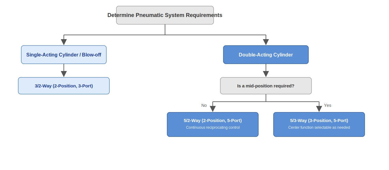
When selecting a pneumatic solenoid valve, in addition to confirming the actuation method — direct-acting or pilot-operated — it is also necessary to understand the difference between Ways and Positions.
These two specifications represent the number of fluid connections on the valve body and the number of positions to which the spool can switch. They are important factors in determining valve function and pneumatic circuit configuration.
- Ways: Refers to the number of fluid connections on the solenoid valve, such as the supply port (P), working ports (A/B), and exhaust ports (R/S). The actual configuration depends on the valve structure and function.
- Positions: Refers to the number of operating positions to which the spool can switch inside the valve body. Different positions correspond to different pneumatic flow paths. Common configurations include 2-position and 3-position valves.
For example, a common 5/2 solenoid valve represents 5 ways and 2 positions, meaning that it has five fluid connections and two spool operating positions.
A 5/3 solenoid valve represents 5 ways and 3 positions, meaning that it has three operating positions and allows the pneumatic condition of the center position to be configured according to application requirements.
How Should You Choose Between Normally Open (NO) and Normally Closed (NC)?
In addition to the number of ways and positions, solenoid valves have another specification that is often overlooked but is directly related to whether the equipment remains safe when power is lost:
Normally Open (NO) and Normally Closed (NC)
- Normally Closed (NC): The valve port remains closed when de-energized and opens when the coil is energized. When power is lost, the pneumatic circuit is automatically shut off.
- Normally Open (NO): The valve port remains open when de-energized and closes when the coil is energized. When power is lost, the pneumatic circuit remains open.
The key consideration is not performance, but rather: if power is lost or the control signal is interrupted, which state should the equipment remain in to ensure safety?
- If the air supply must be shut off immediately during a power failure to prevent unintended cylinder movement or uncontrolled pressure release → Select NC. This is also the default choice for many safety interlock circuits and fixture release mechanisms.
- If airflow must remain available during a power failure so that a certain operation can continue, such as maintaining clamping force or preventing a workpiece from falling → Select NO.
In practice, Normally Open and Normally Closed configurations should not be selected independently. They must be considered together with the number of ways and positions discussed above.
In addition, 5/3-way valves include different center functions. As explained below, these functions also address similar power-loss safety logic and should be confirmed during valve selection.
Common Solenoid Valve Configurations
The number of positions and ways of a pneumatic solenoid valve directly affects how the pneumatic circuit is controlled.
Common configurations include 3/2-way, 5/2-way, and 5/3-way valves, which should be selected according to the cylinder type and control requirements.
Quick comparison of common valve types
Valve type | Operating positions | Port configuration | Common applications |
|---|---|---|---|
3/2-Way | 2 positions | P, A, R | Single-acting cylinders, pneumatic valves, pilot control |
5/2-Way | 2 positions | P, A, B, R, S | Double-acting cylinders |
5/3-Way | 3 positions | P, A, B, R, S | Double-acting cylinders requiring center-position control |
3/2-Way
A 3/2-way solenoid valve has two operating positions and three ports, typically including:
- P: Supply port
- A: Working port
- R: Exhaust port
By switching the spool between two operating positions, the valve controls the supply and exhaust of compressed air. It is suitable for pneumatic circuits involving single-direction actuation.
Common applications include single-acting cylinders, pneumatic valves, pneumatic fixtures, and pilot control for other pneumatic components.
5/2-Way
A 5/2-way solenoid valve is one of the most common configurations for controlling double-acting cylinders. It has two operating positions and five ports:
- P: Supply port
- A, B: Working ports
- R, S: Exhaust ports
By switching the spool, compressed air is alternately supplied to either side of the cylinder while air on the opposite side is exhausted. This controls the extension and retraction of the double-acting cylinder.
Common applications include double-acting cylinders, pneumatic slides, pneumatic fixtures, and reciprocating motion control in automated machinery.
5/3-Way
A 5/3-way solenoid valve has three operating positions and five ports, typically including:
- P: Supply port
- A, B: Working ports
- R, S: Exhaust ports
The spool position is controlled by solenoid coils at both ends. Depending on the center function, the valve can maintain, release, or adjust the force condition of the cylinder when the control signal is interrupted.
Common applications include double-acting cylinders, pneumatic equipment requiring intermediate stopping, applications requiring cylinder load release, and equipment requiring greater resistance to external forces acting on the cylinder.
Center function | Center position condition | Cylinder condition |
|---|---|---|
Closed Center | P, A, B, R, and S are all closed. | The pneumatic circuits on both sides of the cylinder are isolated, which can reduce cylinder movement. |
Exhaust Center | A and B are connected to the exhaust ports. | Pressure on both sides of the cylinder is released, allowing the cylinder to remain in a relatively free state. |
Pressure Center | P is connected to A and B. | Supply pressure is maintained on both sides of the cylinder, increasing its ability to resist movement caused by external forces. |
Note: A closed center is not equivalent to mechanical locking. If the equipment involves vertical loads, falling loads, or personnel safety, mechanical locking or other appropriate safety measures should still be used.
Port Size, Flow Capacity, and Cv Value: How Can You Determine Whether the Valve Capacity Is Sufficient?
When selecting a pneumatic solenoid valve, the required flow rate should be calculated. Preliminary selection can also be made based on piping size and application requirements, followed by further confirmation of operating pressure, required flow rate, valve flow capacity, and system pressure differential.
Using common specifications from Tai-Huei’s AD/AS Series as examples, different port sizes can be used as the following application selection references:
Size | Port size | Recommended applications and selection reference |
|---|---|---|
302 | PT 1/4" | Recommended applications include small cylinders, precision fixtures, single-acting cylinders, and pilot control. Suitable for pneumatic circuits with relatively low flow requirements. |
303 | PT 3/8" | Recommended applications include general industrial automation equipment, packaging machinery, and general cylinder control. It has a wide application range and can be used as a common specification for general equipment. |
304 | PT 1/2" | Recommended applications include medium-sized double-acting cylinders and automated equipment with higher flow requirements. When system flow requirements increase, larger-port specifications can be evaluated first. |
Note: The information above provides only a preliminary reference for selection based on port size and application. Connection size is not equivalent to the actual flow capacity of a solenoid valve.
Actual flow capacity is also affected by factors such as operating pressure, internal valve passages, spool structure, and allowable pressure differential.
Therefore, flow requirements should not be determined solely based on piping size. The Cv value, flow characteristics, or pressure-differential-versus-flow curves provided in the product specifications should also be reviewed.
Pneumatic Flow Cv Calculation Formula
If the selected Cv value is too small, cylinder movement will become slow. If it is too large, compressed-air capacity and installation space may be unnecessarily wasted. The basic flow calculation formula is as follows:
Q = 19.8 × Cv × P₁ × √(ΔP / T)
- Q: Air flow rate (L/min)
- Cv: Flow coefficient
- P₁: Absolute inlet pressure (bar)
- ΔP: Pressure differential across the valve (bar)
- T: Absolute temperature (K)
If you are unsure which specification is suitable, you can provide information such as cylinder bore size, operating pressure, operating speed, piping size, and expected operating frequency. Tai-Huei can assist in confirming a suitable solenoid valve specification based on the actual application conditions.
AS Series vs. AD Series Pneumatic Solenoid Valve Specification Comparison
Both the AS Series and AD Series from Tai-Huei Hydraulic are direct-acting pneumatic solenoid valves. The appropriate series can be selected according to the installation method, available space, and application requirements.
The following summarizes the main specification and application differences between the two series to help you complete valve selection more efficiently.
Specification / attribute | AS Series pneumatic solenoid valve | AD Series pneumatic solenoid valve |
|---|---|---|
Product positioning | Compact design suitable for limited installation spaces and centralized pneumatic circuit configurations. | Suitable for general industrial automation equipment and pneumatic control circuits. |
Valve body construction | Aluminum alloy valve body with a separate body and base design for convenient installation and piping. | Aluminum alloy valve body with a separate body and base design for convenient installation and maintenance. |
Response time | ≤ 0.03 seconds | ≤ 0.03 seconds |
Operating pressure | 0–10 kgf/cm² | 0–10 kgf/cm² |
Maximum operating frequency | 360 cycles/minute | 360 cycles/minute |
Applicable medium | Compressed air filtered to 40 μm or below. | Compressed air filtered to 40 μm or below. |
Typical applications | Precision inspection equipment, semiconductor peripheral equipment, medical automation equipment, robotic fixtures, dispensing equipment, and similar applications. | Packaging machinery, printing equipment, electronic component assembly equipment, cylinder control circuits, and similar applications. |
How Should You Choose Between AD and AS?
If installation space is limited and multiple solenoid valves need to be arranged in a centralized configuration, the AS Series can be evaluated first.
For general industrial automation equipment, packaging equipment, or cylinder control circuits, the AD Series can be selected according to actual piping, flow, and installation requirements.
However, actual valve selection should not be based solely on the series name. Operating pressure, required flow rate, port specifications, voltage, wiring method, and installation space should also be confirmed in order to select the appropriate product.
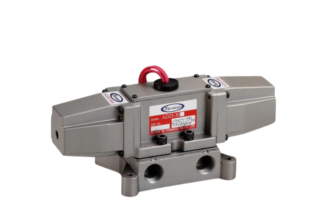
Detailed specifications: AD Series Pneumatic Solenoid Valve Detailed Specifications
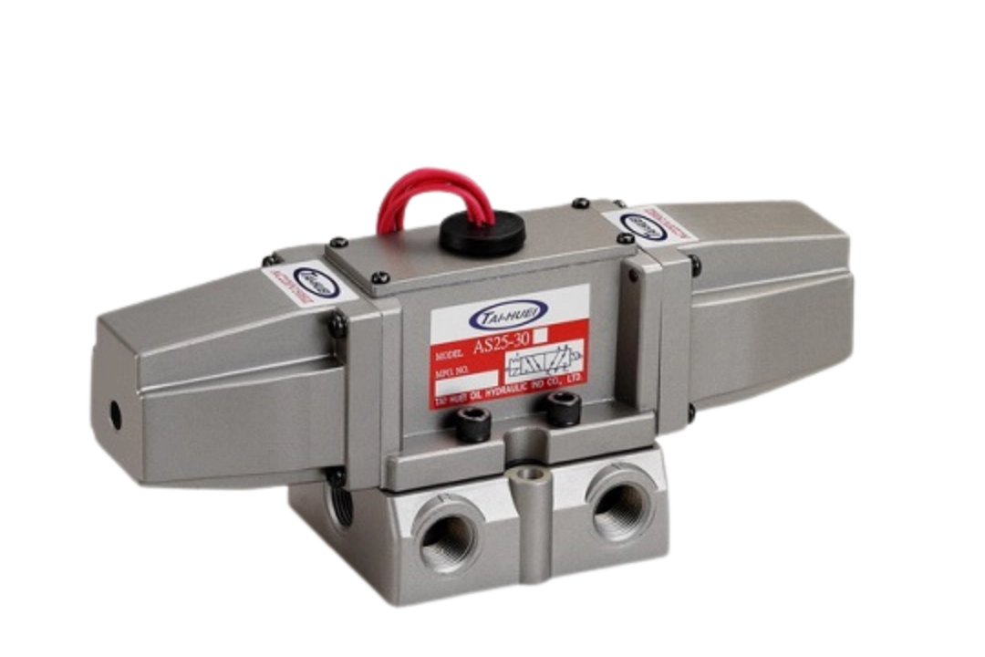
Detailed specifications: AS Series Pneumatic Solenoid Valve Detailed Specifications
Common Pneumatic Solenoid Valve Problems and Maintenance
Even high-quality pneumatic solenoid valves may experience problems such as abnormal operation, coil overheating, or air leakage after long-term operation if compressed-air quality is poor, installation and operation are improper, or regular maintenance is neglected.
The following summarizes three common pneumatic solenoid valve problems and their corresponding troubleshooting and preventive measures.
Failure symptom | Possible cause | Troubleshooting and prevention |
|---|---|---|
Solenoid valve sticking | Moisture, dust, or other contaminants in the compressed air. | Install an F.R.L. unit or appropriate air filtration equipment, and regularly drain moisture and clean the system. |
The spool or valve seat is contaminated by foreign particles, resulting in poor movement. | Remove and clean the spool and valve seat, and confirm the cleanliness of the compressed air. If the product requires lubrication, use pneumatic lubricating oil according to the manufacturer’s specifications. | |
Abnormal coil heating or coil burnout | Excessive supply voltage, voltage fluctuations, or a mismatch between the supply voltage and the coil’s rated voltage. | Use a power supply that meets the coil specifications and confirm both the rated voltage and the actual supply voltage. |
Spool sticking, or the solenoid valve remaining in an abnormal operating condition for extended periods. | Check whether the spool moves smoothly and eliminate foreign particles, contamination, or mechanical sticking problems to prevent the coil from remaining in an abnormal overheating condition for extended periods. | |
Minor air leakage | Worn, aged, or damaged sealing rings. | Inspect the condition of the seals and replace O-rings or seal kits when necessary. |
Foreign particles trapped on the valve seat or sealing contact surfaces. | Remove and clean the valve seat and sealing contact surfaces, and confirm the cleanliness of the compressed air. | |
Poor sealing at piping connections or threaded connections. | Inspect piping fittings, threads, and sealing materials, and confirm that installation has been carried out correctly. |
Three Practical Maintenance Recommendations
- Proper Air Preparation (F.R.L.): According to the requirements of the pneumatic system and solenoid valve, install an air filter, regulator, and, when necessary, a lubricator upstream to reduce the risk of moisture, dust, and contaminants entering the solenoid valve. If the solenoid valve is designed for non-lubricated operation, it should be used according to the manufacturer’s specifications, and lubricating oil should not be added arbitrarily.
- Regularly Check the Supply Voltage: Solenoid valve coils should be supplied with power that meets their rated specifications, and the actual supply voltage should be checked regularly to ensure stability. The allowable voltage range of some coils may reach ±10% of the rated voltage. However, the actual allowable range should always be based on the coil manufacturer’s specifications. Excessive voltage may cause coil overheating, while insufficient voltage may result in inadequate electromagnetic force and prevent the valve from operating properly.
- Establish a Regular Preventive Maintenance Program: For pneumatic solenoid valves that operate at high switching frequencies or continuously for extended periods, regular inspections should be scheduled according to equipment usage frequency and operating conditions. Inspection items may include valve operation, directional switching sound, seal condition, air leakage, and coil temperature rise. Abnormal conditions should be identified and addressed as early as possible.
Through regular inspection and proper compressed-air management, problems such as solenoid valve sticking, coil overheating, and air leakage can be effectively reduced. This helps extend component service life and maintain stable operation of pneumatic equipment.
Conclusion and Professional Selection Recommendations
Pneumatic solenoid valves are important components used to control pneumatic circuits in automated equipment. Their selection directly affects equipment operating stability, response speed, and service life.
From confirming valve types and way configurations such as 2/2, 3/2, and 5/2, to evaluating actual flow requirements, operating pressure, and switching frequency, and confirming the safe state that the pneumatic circuit should maintain during power loss (NC/NO), then selecting an appropriate solenoid valve series according to the operating environment — every specification should match the actual requirements of the equipment.
Tai-Huei’s AS Series and AD Series pneumatic solenoid valves provide corresponding product options for different pneumatic control requirements, helping equipment manufacturers and users establish stable and reliable pneumatic control systems.
If you have any questions regarding pneumatic solenoid valve selection, specification confirmation, or practical applications, please visit the official Tai-Huei website or contact our professional team. Based on the equipment’s operating pressure, flow rate, voltage, piping method, and operating environment, we can assist you in selecting a suitable solenoid valve product.