
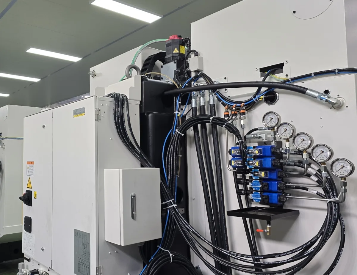
This is a CNC vertical machining center built by a Korean machine tool builder.
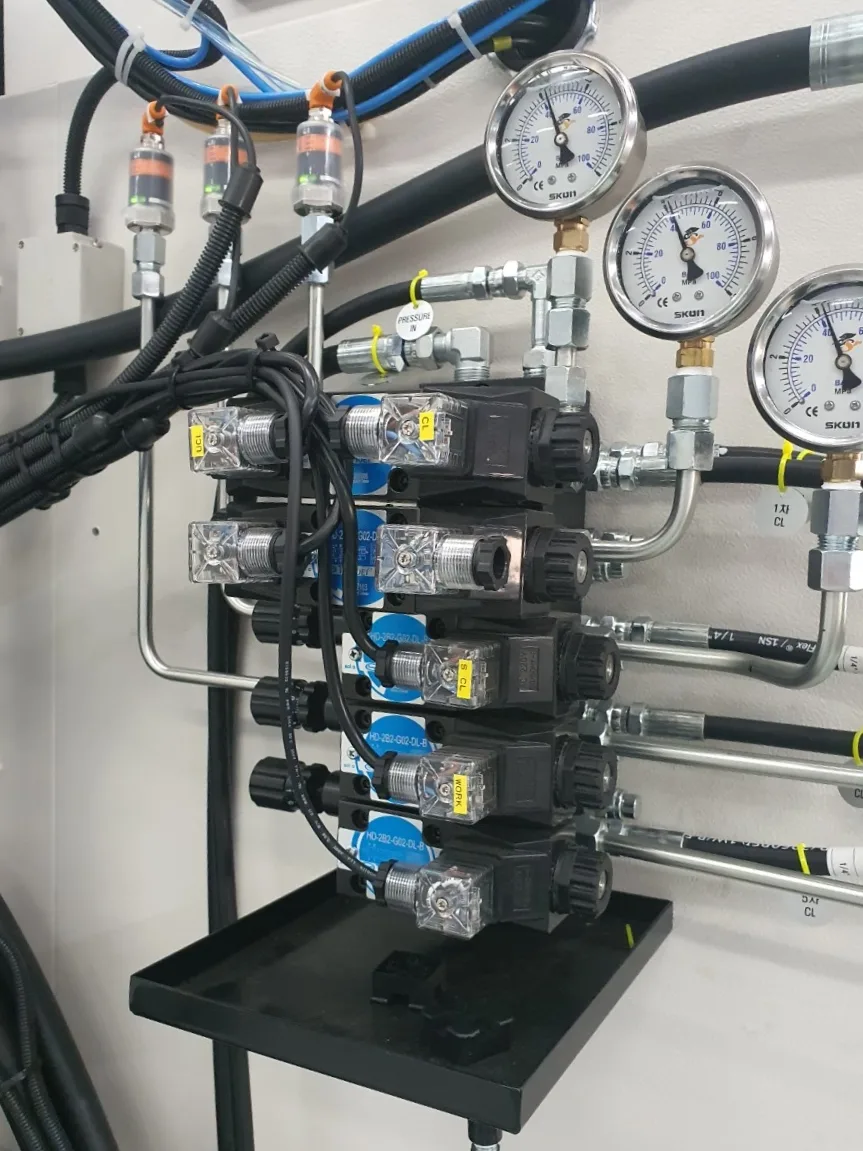
On the back of the machine, the hydraulic workholding fixture is controlled by five stacked solenoid directional valves: Tai-Huei HD-2B2-G02-DL-B. There are five pressure gauges beside the stack, three pressure switches above it, and every hose is labeled.
If you are working on hydraulic fixture design, or deciding which hydraulic solenoid valve to use on a machine tool circuit, this case study uses photos from an actual installation to show how the G02 valves are arranged, why the layout is easy to service, and what to prepare to check whether they fit your machine.
Sources: photos taken inside a Korean machine tool builder's plant (September 2026, published with the customer's permission) and the Tai-Huei G02/G03 catalog.
Case Summary
Customer | Machine tool builder in Korea (plant photos published with permission) |
|---|---|
Machine | CNC vertical machining center built by the customer; hydraulic workholding valve stack |
Valve model | Tai-Huei HD-2B2-G02-DL-B solenoid directional valve (G02 size, DL indicator-light connector) |
Configuration | Five valves stacked on a multi-station subplate; one pressure gauge per circuit; three pressure switches above the stack |
Specs (Tai-Huei catalog) | Max. flow 60 L/min; max. operating pressure 315 kgf/cm² (approx. 309 bar); mounting interface ISO 4401-03 |
Supply | Through our distributor in Korea |
Key Points
- One clamping action, one solenoid valve. When clamping runs in stages, each circuit has its own valve and the controller sets the sequence.
- Several valves share one subplate. The G02 series uses an ISO 4401-03 mounting interface, so the valves share the subplate's pressure and tank ports, and each valve connects to its cylinder through its A and B work ports.
- Gauges are for people; pressure switches are for the controller. If clamping pressure has not reached its set point, the controller can block the spindle from starting the cut, reducing the risk of machining an unclamped part.
- The indicator light is a starting point. A lit light means the connector is receiving power; you still need to confirm the spool has shifted. No light means check power, the control signal and wiring first.
Hydraulic Workholding Solenoid Valves: Common Questions
One clamp is not holding, but the valve's indicator light is on. Where do I start?
Check the actual clamping pressure on that circuit first, then work through the cylinder, the lines and the valve.
- Gauge shows pressure but the cylinder is weak: check the cylinder for internal or external leakage, look for problems in the lines and fittings, and confirm the supply pressure suits the clamping requirement.
- Gauge shows no or low pressure: check the supply, check whether contamination is sticking the spool, and check the O-rings between valve and subplate for damage, misalignment or poor sealing.
- Light is on but the spool may not have shifted: confirm the actual coil voltage, spool movement and that the flow path is clear. A lit light does not mean the spool has completed its shift.
- Light is off: measure the actual voltage at the coil connector and check the control signal, wiring and coil rating.
Confirm the supply and pressure on that circuit first, then narrow the fault down step by step. Stop the machine and relieve system pressure before opening hydraulic lines or removing a valve.
Should a fixture circuit use G02 or G03?
It depends on the flow you need. Per the Tai-Huei catalog, G02 has a maximum flow of 60 L/min and G03 has 100 L/min, both with a maximum operating pressure of 315 kgf/cm² (approx. 309 bar).
Calculate the required flow from cylinder bore and actuation speed first; move to G03 when the requirement exceeds G02, rather than choosing the larger size just because it is a fixture circuit. Pressure drop and supply conditions also matter.
What do I need to send to order a valve with the same spec?
Photograph three things: the model number or nameplate on the valve body, the voltage marked on the coil, and the connector type.
Each Tai-Huei valve carries a body code on the valve body that traces its manufacturing date and spool. Include a clear photo of it to reduce the risk of getting the wrong model, voltage or spool function.
Why fit a gauge on each circuit? Isn't one main gauge enough?
A main gauge shows supply pressure; it cannot tell you whether an individual clamping circuit is working. With a gauge on each circuit, you can compare readings when one cylinder loses grip and tell whether the problem is in the supply, a single circuit, or the cylinder and lines. A gauge shows pressure at its own location, so read it together with the cylinder's actual movement.
If one stacked valve fails, does the whole stack have to come off?
Not necessarily. When each valve is bolted to the subplate independently and space and piping allow, you can usually change just the failed valve.
Stop the machine, isolate energy sources and relieve system pressure first, and place a drip tray underneath. Make sure the new valve matches the model, spool function, coil rating and mounting interface, that the O-rings are intact and seated, and then run a test cycle and check for leaks.
How to read the labels on site
Label on site | Literal meaning | What the layout suggests |
|---|---|---|
| UCL / CL | Unclamp / Clamp | Likely the unclamp and clamp commands; which coil end is which must be confirmed from the wiring |
| 1차 CL, 3차 CL, 5차 CL | Clamp stage 1, 3, 5 | Staged clamping is marked on site; the actual action assignment follows the hydraulic and control logic |
| WORK | Work / workpiece | A circuit related to the work sequence; the exact controlled device needs confirmation |
| PRESSURE IN | Pressure inlet | Marks the supply inlet |
Detail 1: Why Stack the Valves Instead of Piping Each One?
A shared subplate simplifies piping and cuts external fittings and potential leak points.
The G02 / D03 series uses a mounting interface to ISO 4401-03 and fits multi-station subplates with the same interface, so several solenoid valves share the subplate's internal pressure and tank galleries. Each valve then connects to its cylinder or work circuit through its A and B work ports.
The result is a compact solenoid valve manifold that is easier to service; how much piping you actually save depends on the subplate design and circuit layout.
Detail 2: A Gauge on Each Circuit Saves Troubleshooting Time
When a fixture loses clamping force, the first thing to establish is: which circuit has the pressure problem?
A main gauge alone cannot show whether an individual circuit is working; on this valve stack each circuit has its own gauge, so a technician can compare readings and go straight to the faulty circuit without opening lines first.
(A larger hydraulic unit at the same plant follows the same approach: two rows of valves with two rows of gauges, 16 gauges in all, so each circuit's pressure is read separately.)
Detail 3: Pressure Switches Turn "Pressure Reached" into a Control Signal
Gauges are read by people on the shop floor; a pressure switch sends an on/off signal to the control system when pressure reaches its set point.
From their appearance, the three green-lit components above the stack appear to be pressure switches; their exact function should be confirmed from the part numbers and wiring.
The controller can include the pressure switch signal in the machining interlock: if clamping is not confirmed, the spindle does not start, which helps prevent scrapped parts, broken tools, or a part leaving the fixture.
Reaching set pressure does not by itself mean the part is correctly located; the actual interlock conditions depend on the machine design and risk assessment.
Detail 4: DL Indicator-Light Connectors for First-Line Electrical Checks
These solenoid valves use DL indicator-light connectors rated IP65. The light on each coil connector helps technicians check the electrical control state quickly.
The light splits a fault into electrical or hydraulic, but a lit light is a first clue and does not prove the spool has shifted; the full troubleshooting order is in the first question above.
Detail 5: What Is the Black Tray Under the Valves For?
A tray like this catches oil released when lines are opened, a valve is changed or the stack is serviced, keeping oil off the machine and floor and away from the electrical equipment below.
On this machine there is also a drain valve at the bottom of the tray to empty the collected oil.
Detail 6: Labels on Each Hose and Coil
The hoses, coil connectors and gauges on this valve stack are all labeled. Years into service, the person maintaining the machine may not be the one who plumbed it, and clear labels cut the time spent checking drawings and reduce the risk of swapping a line or a wire.
The hose jacket is also printed with its specification: EN 853 1SN, 1/4 in, 225 bar.
Do not size hoses by the normal working pressure on the gauge alone; check the peak pressures the system can see, and follow the manufacturer's ratings.
What Tai-Huei Does Before the Valves Ship
Pressure, flow and electrical tests to our internal inspection procedure before shipment.
Each valve carries a body code on the valve body, and our traceability records link it to the manufacturing date and spool.
Will Tai-Huei G02 Fit Your Machine?
If your circuit uses an ISO 4401-03 mounting interface and each circuit needs 60 L/min or less, G02 is within range for evaluation; check the other conditions in the table below, where the right column lists what to confirm during hydraulic fixture design and before quoting.
Your machine | How G02 matches | Confirm first |
|---|---|---|
| Multi-stage clamping that must run in sequence | One valve per action, stacked on one subplate | Number of clamping actions and their order (locating and support count too) |
| Directional control on a fixture or machine tool | ISO 4401-03 mounting interface; fits subplates with the same interface | Subplate port pattern and port sizes |
| Up to 60 L/min per circuit | G02 max. flow 60 L/min; for higher flow, evaluate G03 (100 L/min) | Required flow from cylinder bore and speed |
| Different actions need different de-energized states | A range of spool options | Whether each cylinder must hold, release or do something else on power loss or E-stop |
| Technicians need to tell electrical from hydraulic faults quickly | DL indicator-light connector (IP65); the light gives a first indication | Coolant spray or dust at the mounting location |
| Single valves changed later | Body code traces manufacturing date and spool | Provide model and body code when ordering |
| Clamping pressure must be confirmed | Room for pressure switches on the stack | Spare inputs on the controller |
Tai-Huei provides technical support and a range of spool options. Gather the items in the right column and send us an inquiry, or email [email protected], and we will help confirm spool functions, valve size and piping for your action sequence.