
The control panel receives the signal that the solenoid valve is energized, yet the hydraulic cylinder stops halfway. The PLC never receives an in-position signal, and the line has to stop for inspection.
When a standard solenoid valve is energized, the only thing confirmed is that the coil has received an electrical signal. It does not mean the spool inside the valve has actually shifted. Whether the spool is sticking because of contaminated oil, sludge or other causes, and whether it has really moved to the intended position, cannot be confirmed directly from the control side.
A spool position monitored directional valve has a position sensor mounted on the valve body that monitors the actual position of the spool. A position confirmation signal is output only after the spool has moved to the set position, so the PLC can tell whether the spool is really in position, not just whether the coil is energized.
If what matters most for the machine is whether the PLC can confirm that the spool has actually shifted, the focus should be on position feedback, not only on confirming that the coil is energized.
The first half of this article covers the spool position monitored directional valve. The second half covers the AB manual positioning series.
Spool Position Monitored Directional Valve: Signal and Wiring
The spool position monitored directional valve outputs an on/off signal (in position / not in position), not a continuous position value. Confirm this before planning the PLC inputs.
It is a wet-armature solenoid directional valve fitted with a position sensor. After the coil is energized, the sensor triggers only when the spool has shifted to the set stroke point. If the spool sticks because of contamination or does not reach position for any other reason, the contacts do not switch and the PLC does not receive an in-position signal.
The sensor has two outputs, and the switching point tolerance is within 0.5 mm. There are 4 wires plus a shield wire, defined as follows:
- Red: VCC, 18–24 V DC
- Black: GND
- Blue: Output A (normally closed contact; opens when the spool reaches the trigger point)
- White: Output B (normally open contact; closes when the spool reaches the trigger point)
- Shield: connect to the housing
Electrical ratings: recommended output current ≤50 mA per channel, maximum output current 400 mA, maximum load output voltage drop ≤6 V. Ambient temperature 0–50°C. The sensor has a stainless steel housing with IP67 protection. The trigger point is set before the valve leaves the factory.
In other words, the coil signal only shows that the electrical side has acted. The change in the two contact outputs is what shows that the spool has reached the set position.
For solenoid valve connector types and protection ratings, see Hydraulic Solenoid Valve Connectors: Comparing 5 Wiring Types, IP Ratings and Selection Criteria.
To confirm how these two signals should be wired into the interlock logic of your control panel, ask us on LINE.
Spool Position Monitored Directional Valve: G02, G03, G04 and G06 Sizes
The spool position monitored directional valve is available in four sizes: G02, G03, G04 and G06. The mounting surface conforms to ISO 4401:2005. The maximum operating pressure of all four sizes is 315 kgf/cm², and the flow rate is the same as the standard solenoid directional valve of the same size. When selecting, confirm the size first, then the available spool.
Size | Flow rate | Spool | Back pressure | Switching frequency | Model code |
|---|---|---|---|---|---|
| G02 (CETOP 3) | 60 L/min | 3C2 | 110 kgf/cm² | 240 cycles/min | HD-3C2-G02-DL-B-P-AC/DC |
| G03 (CETOP 5) | 100 L/min | 3C2 | 130 kgf/cm² | 240 cycles/min | HD-3C2-G03-DL-B-P-AC/DC |
| G04 (CETOP 7) | 300 L/min | 2B2, 3C4 | External drain 210 kgf/cm² Internal drain 140 kgf/cm² | 120 cycles/min | HD-***-G04-*-*-P |
| G06 (CETOP 8) | 500 L/min | 2B2, 3C4 | External drain 210 kgf/cm² Internal drain 140 kgf/cm² | 120 cycles/min | HD-***-G06-*-*-P |
G02 Spool Position Monitored Directional Valve
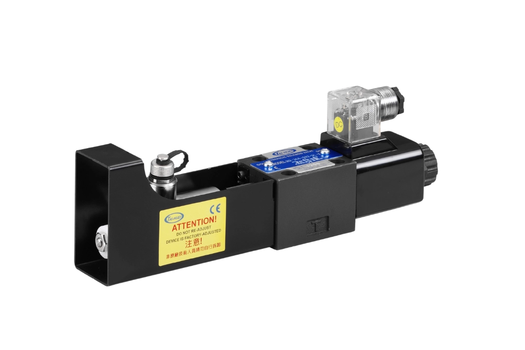
G02 (D03, CETOP 3, NG6, 1/4") is the smallest of the four sizes. The valve body is a wet-armature solenoid directional valve.
Rated flow: 60 L/min
Spool: 3C2 only
Back pressure: 110 kgf/cm²
Switching frequency: 240 cycles/min
Connector: DL DIN plug
Model: HD-3C2-G02-DL-B-P-AC/DC
G03 Spool Position Monitored Directional Valve
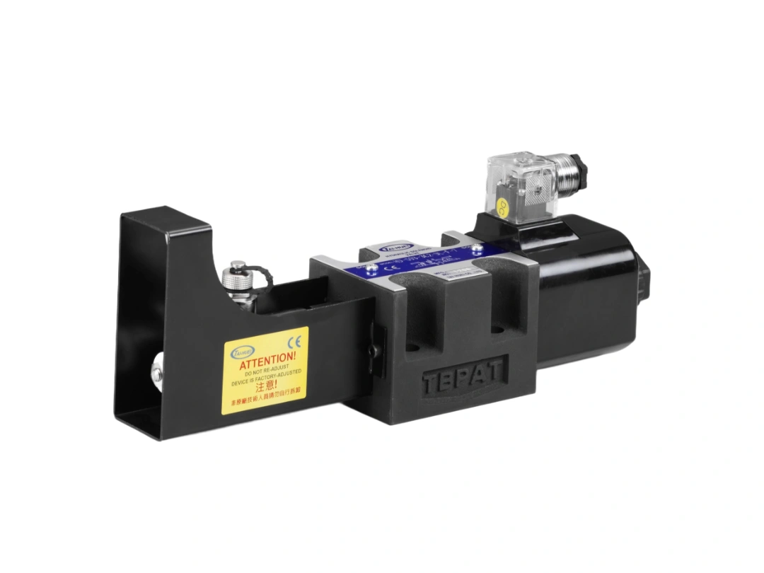
G03 (D05, CETOP 5, NG10, 3/8") is also a wet-armature solenoid directional valve.
Rated flow: 100 L/min
Spool: 3C2 only
Back pressure: 130 kgf/cm²
Switching frequency: 240 cycles/min
Connector: DL DIN plug
Model: HD-3C2-G03-DL-B-P-AC/DC
G04 Spool Position Monitored Directional Valve
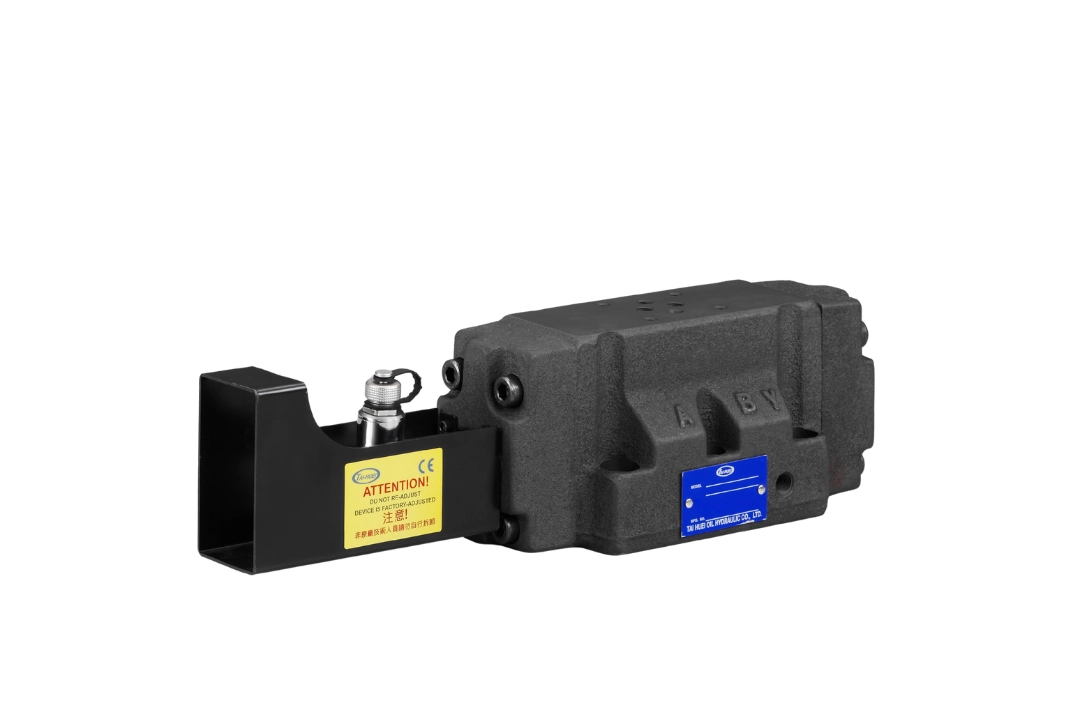
G04 (D07, CETOP 7, 1/2", 16 mm bore) is a solenoid-controlled pilot-operated valve.
Rated flow: 300 L/min
Spool: single solenoid 2B2 or double solenoid 3C4
Pilot: P internal pilot or *P external pilot
Drain: D internal drain or *D external drain
Pilot pressure: min. 5, max. 250 kgf/cm²
Back pressure: external drain 210 kgf/cm², internal drain 140 kgf/cm²
Switching frequency: 120 cycles/min
Model (2B2 spool as an example): HD-2B2-G04-*-*-P
G06 Spool Position Monitored Directional Valve
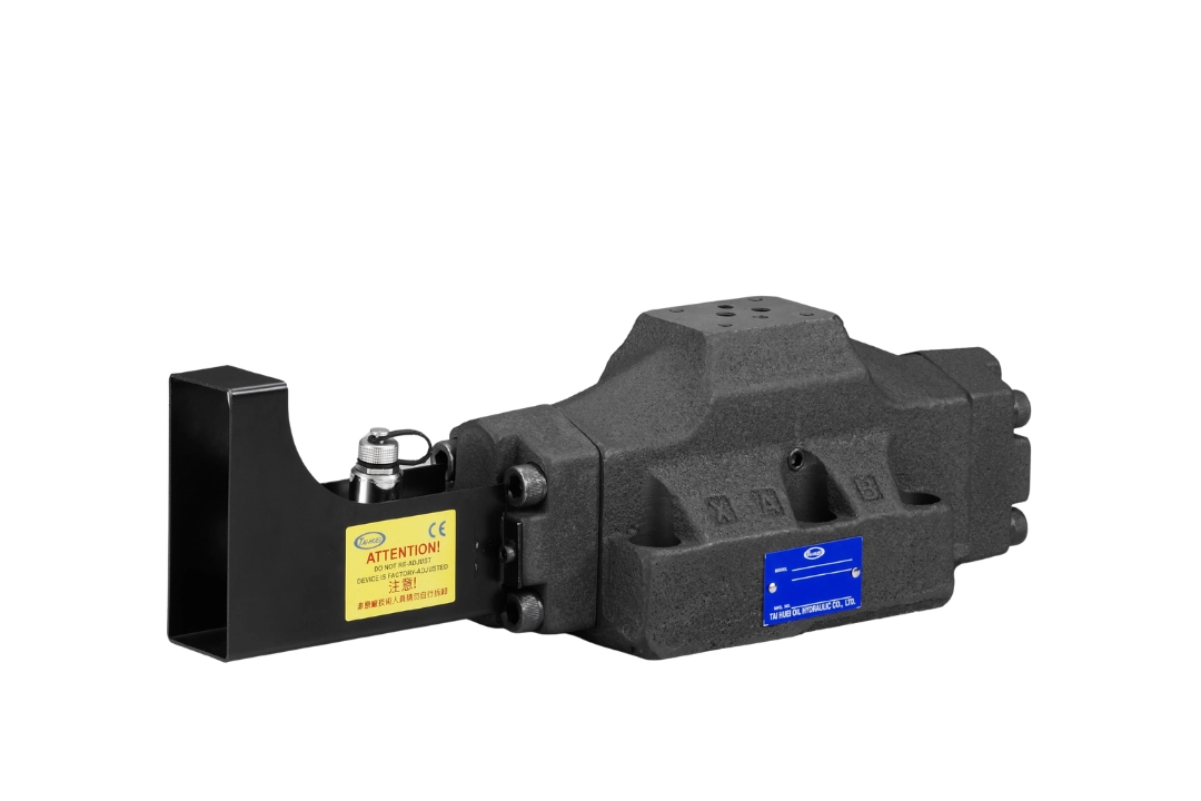
G06 (D08, CETOP 8, 3/4", 25 mm bore) has the highest flow rate of the four sizes and is also a solenoid-controlled pilot-operated valve. Rated flow: 500 L/min
Spool: single solenoid 2B2 or double solenoid 3C4
Pilot: P internal pilot or *P external pilot
Drain: D internal drain or *D external drain
Pilot pressure: min. 5, max. 250 kgf/cm²
Back pressure: external drain 210 kgf/cm², internal drain 140 kgf/cm²
Switching frequency: 120 cycles/min
Model (2B2 spool as an example): HD-2B2-G06-*-*-P
In the model code, B stands for the B series and P for the position sensor. In the G04 and G06 model codes, the two asterisks (*) are filled in with the pilot type and the drain type.
Coil voltage options: AC110 (50 or 60 Hz), AC220 (50/60 Hz), DC12V, DC24V, RFN110V, RFN220V.
To compare mounting surfaces and flow rates by size, see How to Select Hydraulic Solenoid Valve Size: Flow Rating Chart and ISO 4401 Mounting Interfaces.
Spool Position Monitored Directional Valve: Installation and Use
The spool position monitored directional valve contains a position sensor. Note the following during installation and use:
- If the sensor output drives an inductive load such as a relay coil or a motor, add a surge protection circuit to the external circuit.
- Filtration ratio: βx = 75, x = 25 μm.
- TAI-HUEI uses AW-46 anti-wear hydraulic oil (ISO VG46) in its own facility.
- The hydraulic system should not subject the spool to shock or vibration.
- During handling and installation, do not let the valve fall from a height of more than 30 cm onto a hard surface.
- Do not disassemble the valve, and do not replace any internal or external parts or the throttle yourself.
To confirm the right size and spool for your existing circuit, send us an inquiry with the model code or circuit diagram.
AB Manual Positioning Series: Adjusting Screws on a Solenoid Directional Valve
The AB manual positioning series is a solenoid directional valve fitted with adjusting screws on side A, side B, or both sides. The A, B or AB at the end of the model code shows which side is adjustable. It has no handle and is not a lever-operated manual valve.
Within the series, the small and large sizes serve different purposes. G02 and G03 are for positioning: turning the adjusting screw pushes the spool into position. G04 and G06 are for flow adjustment. When selecting, first decide whether you need to position the spool or adjust the flow, then choose the size. Flow rate and maximum operating pressure are the same as the standard solenoid directional valve of the same size.
Item | G02, G03 | G04, G06 |
|---|---|---|
| Purpose | Positioning: turning the adjusting screw pushes the spool into position | Flow adjustment |
| Connector / pilot and drain | LW or DL connector | P internal pilot, D internal drain |
| Adjusting part | Anodized aluminum alloy adjusting nut, dust- and rust-resistant Does not affect magnetic force output | Special steel adjusting screw, induction hardened Special thread for fine adjustment |
| How to adjust | The nut turns by hand, no tools needed | Square-end screw, adjusted with a common tool |
| Flow adjustment | Not for flow adjustment | Can be used for flow adjustment |
G02 AB Manual Positioning Solenoid Directional Valve
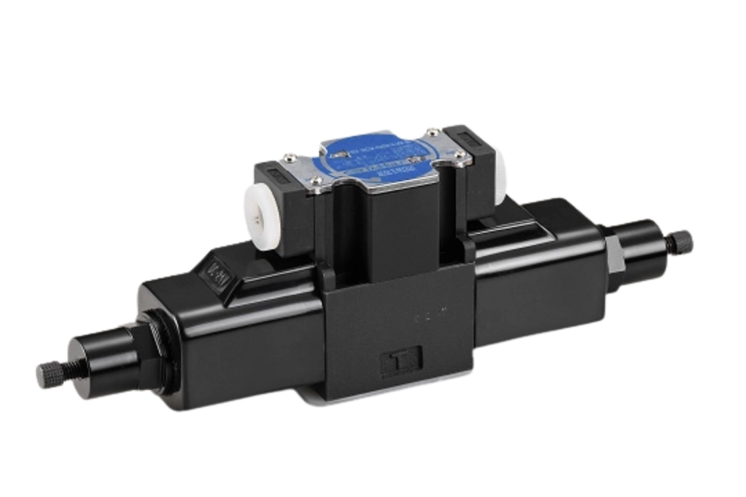
On the G02 (1/4", D03, NG6), the adjusting screw is for positioning, not for flow adjustment.
Anodized aluminum alloy adjusting nut, dust- and rust-resistant, does not affect magnetic force output
The nut turns by hand, no tools needed
Connector: LW terminal box or DL DIN plug
Rated flow: 60 L/min
Model example: HD-***-G02-LW-*-AB-AC/DC
G03 AB Manual Positioning Solenoid Directional Valve
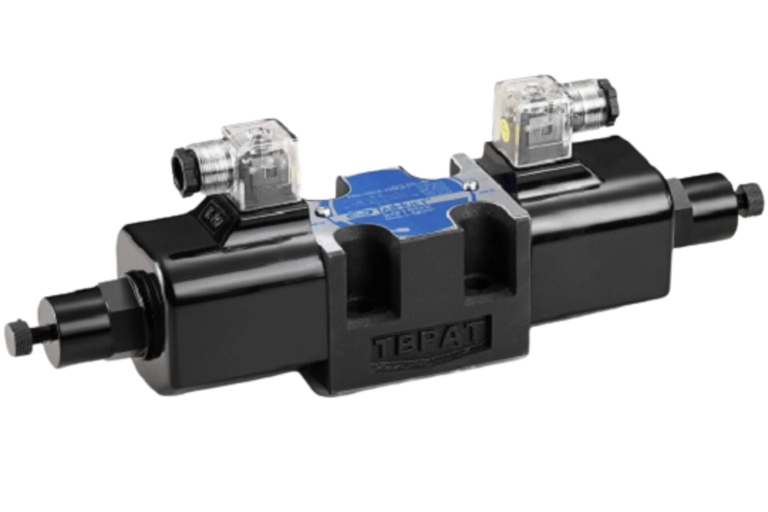
Like the G02, the G03 (3/8", D05, NG10) adjusting screw is for positioning, not for flow adjustment
The adjusting nut is also anodized aluminum alloy and turns by hand
Connector: LW terminal box or DL DIN plug
Rated flow: 100 L/min
Model example: HD-***-G03-DL-*-AB-AC/DC
G04 AB Manual Positioning Solenoid Directional Valve
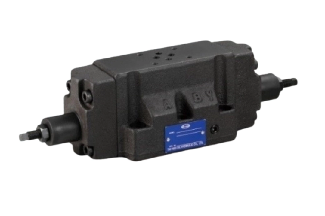
On the G04 (1/2", 16 mm bore), the adjusting screw is for flow adjustment.
Special steel adjusting screw, induction hardened, with a special thread for fine adjustment
Square-end screw, adjusted with a common tool
Pilot: P internal pilot or *P external pilot
Drain: D internal drain or *D external drain
Rated flow: 300 L/min
Model: HD-***-G04-P-D-AB
G06 AB Manual Positioning Solenoid Directional Valve
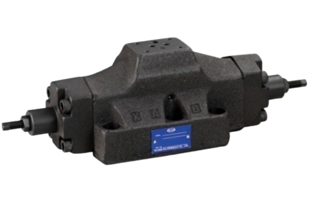
Like the G04, the G06 (3/4", 25 mm bore) adjusting screw is for flow adjustment
Special steel adjusting screw, induction hardened, with a special thread for fine adjustment
Square-end screw, adjusted with a common tool
Pilot: P internal pilot or *P external pilot
Drain: D internal drain or *D external drain
Rated flow: 500 L/min
Model: HD-***-G06-P-D-AB
If you need to adjust flow, choose the G04 or G06. The G02 and G03 adjusting nuts are for positioning only and are not for flow adjustment.
To confirm which adjustment type suits your existing valve, send us an inquiry with the model code you are using now.