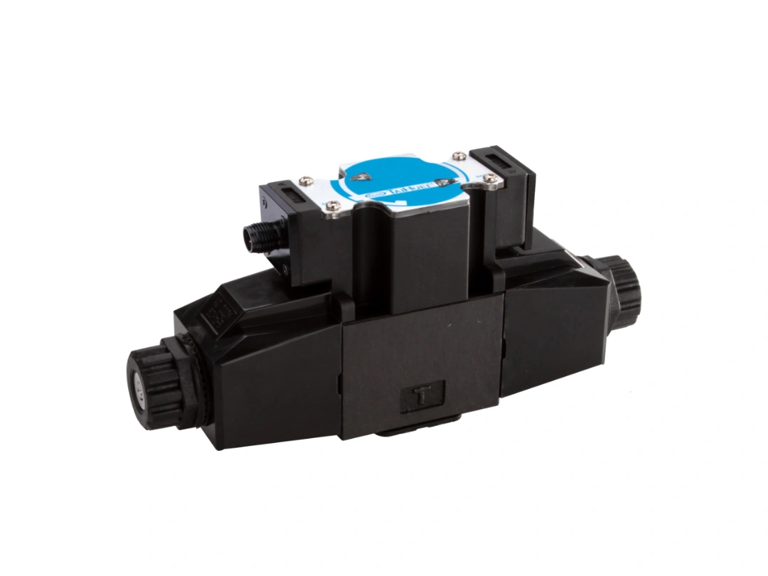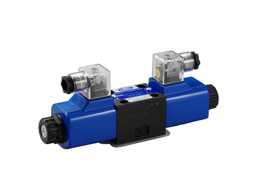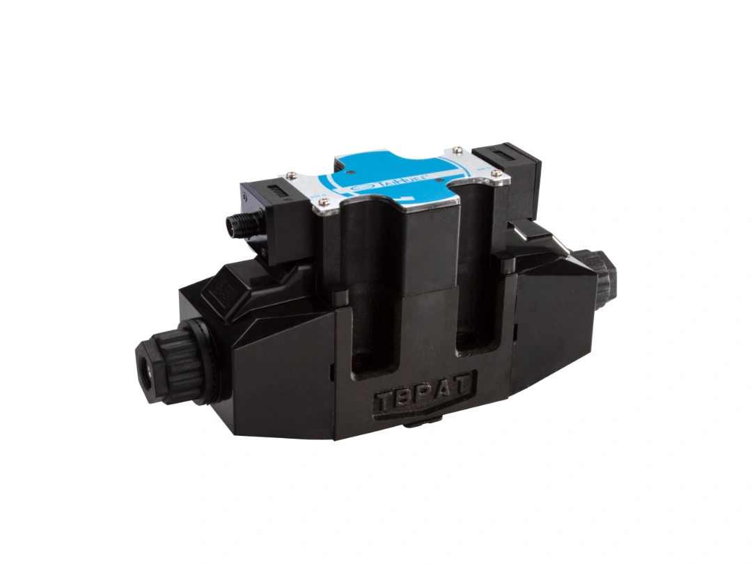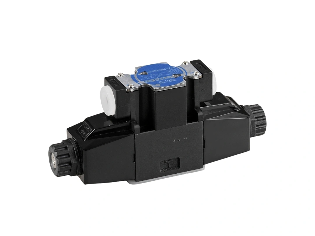
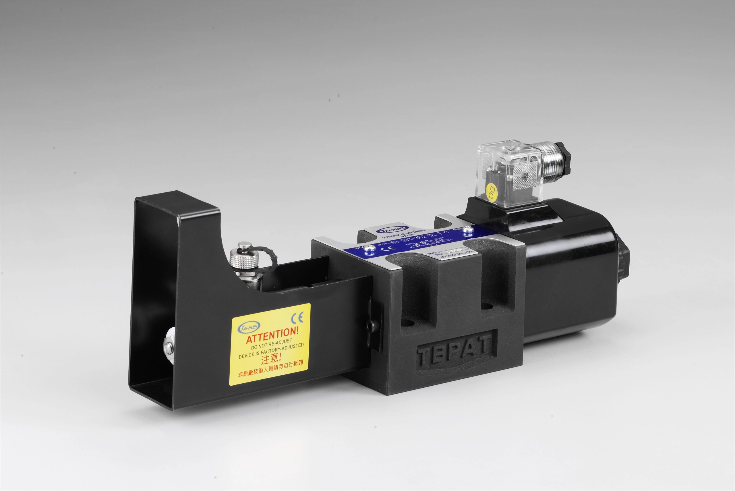
DL DIN PLUG TYPE
HD-3C2-G03-DL-P-AC/DC
Description of Model
Code | Meaning | Options for this model |
HD | Wet-armature solenoid directional valve | HD |
*** | Spool type | 3C2 |
G03 | Valve size | 3/8" (D05 / NG10) |
DL | Wiring connection | DL DIN plug |
B | Series | B: high-efficiency, low-current solenoid directional valve |
P | Position sensor | P (standard) |
AC/DC/RF | Coil voltage | AC110 (50 Hz or 60 Hz), AC220 (50/60 Hz), DC12, DC24, RF110, RF220 |
G03 Specifications
Model | HD-3C2-G03-DL-P-AC/DC |
Spool type | 3C2 |
Mounting interface | ISO 4401-05 (D05 / NG10) |
Max. operating pressure | 315 kgf/cm² |
Max. allowable back pressure (3C2) | 130 kgf/cm² |
Max. flow | 100 L/min |
Switching frequency | 240 cycles/min (AC, DC types) |
Oil temperature range | -15 to +70 °C |
Oil viscosity range | 10 to 400 cSt (ISO VG46, 68) |
Sensor ambient temperature | 0 to 50 °C |
Max. flow, max. operating pressure and back pressure vary with the circuit.
Operation Principle
The built-in position switch monitors the spool position. When the solenoid is energized and the spool shifts to the set stroke point, output A opens and output B closes. If the spool does not reach that point, the switch does not change state.
The switch signal goes to a PLC or industrial computer, which uses it to control or drive hydraulic components and other machine motions.
Features
A. The series is available in 4 sizes: G02, G03, G04 and G06, for different flow requirements.
B. Protection class IP67, stainless steel housing.
C. Electronic Specification
Input Supply Voltage | 18~24VDC(±10%) |
Recommended Output Current per Channel | ≦50mA |
MAX Output Current per Channel | 400mA |
MAX Output Drop | ≦6V |
Switch Point Deviation | ≦0.5mm |
Ambient Temperature | 0~50°C |
Protection Class | IP67 |
D. Statement of Connector and wiring

- VCC (18~24V DC), red wire.
- Output B, White wire.
- GND, Black wire.
- Output A, Blue wire.
- The shield wire connects to the housing.
- This switch is dedicated to stroke-point monitoring.
- When the trigger point is reached, output A (4 pin) non-conductive – normally closed.
- Output B (2 pin) conductive-normally opened.
- The switching point is adjusted by moving the outer tube on the inner tube or by the core thread, and is set at the factory before shipment.
Notes
- When the position switch drives an inductive load, such as a motor or relay coil, opening the load circuit produces a high induced voltage that may damage the switch or shorten the valve life. A surge protection device is recommended.
- Do not disassemble the valve body. Do not replace internal or external components. Do not replace or modify the internal throttle.
- The position switch can only be set and checked by the manufacturer.
- The hydraulic system must keep the spool free from shock and vibration.
- Do not drop the valve onto a hard surface from higher than 30 cm; the built-in sensor may fail.
- Keep the hydraulic oil clean; contamination shortens valve life or causes damage. Use filters with a filtration ratio of βx = 75 (x = 25 μm).
- Use ISO VG32 or ISO VG46 hydraulic oil, or water-glycol fluid.
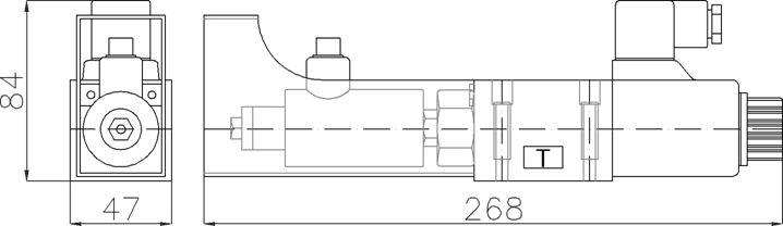
View
 |
 |
 |
 |